Single Phase Motor Timer Connection:
This diagram shows how to make Single Phase Motor Timer Connection. In this circuit, we use, a TP MCB ( Tripple Pole Minature Circuit Breaker ), a timer, an emergency switch, a magnetic contactor, a start switch, a stop switch, and a three-phase motor. This circuit is very simple and easy to make. If you want to know more about this circuit please stay check our youtube video for clear details.
Advertisements
Diagram of Single Phase Motor Timer Connection:

Components needed For this Project:
You can get the components from any of the sites below:
- TP MCB 32A [See Buy Click Amazon]
- 8 Pin Timer 220V AC [See Buy Click Amazon]
- Magnetic Contactor 40A [See Buy Click Amazon]
- 3 Phase Motor (5 HP) [See Buy Click Amazon]
- Emergence Switch [See Buy Click Amazon]
*Please note: These are affiliate links. I may make a commission if you buy the components through these links. I would appreciate your support in this way!
Advertisements
Components used to make the Single Phase Motor Timer Connection:
01. TP MCB:

The full meaning of MCB is Miniature Circuit Breaker for TP MCB. MCB is an electromagnetic switch or device. If for any reason a short circuit occurs in the supply line or load line (line to line or line to neutral) or in case of overload MCB. the MCB automatically trips and disconnects the main line circuit or household power supply Connection. TP MCB In 3 Pole MCB, Switching & Protection is affected in only 3-Phases and the Neutral is not part of the MCB. 3 pole MCB signifies the Connection of Three Wires for a 3-Phase system Red-Yellow-Blue Phase. 3-Phase Supply Only Without Neutral.
02. Timer:
A timer is a type of time-switching device that controls and controls Electrical circuits and electrical and electronic devices through time setting (on/off). The timer is basically 8-pin. Like other controlling devices the timer has a coil and when this coil is magnetized, the timer works on/off. The timer has 2 common ends and each common end has normally close and normally open options. When the timer is set by time, the timer trips at the end of that time and turns the common is normally closed (on) to open (off) and normally open (off) to close (on). This is how the timer works.

03. Magnetic Contactor:

A magnetic contactor is an electromagnetic switching device. It is generally used for controlling 3-phase Motors. The operation of a magnetic contactor is similar to that of a Relay. but a relay is used for low-power or low-voltage connections, and a magnetic contactor is used for high-power or high-voltage connections. As soon as the supply is applied to the magnetic contactor coil. its normally open contacts are closed and normally closed contacts are opened and the associated devices are also operated. This is how a magnetic contactor works.
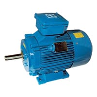
04. 3-Phase Motor:
A 3-phase electric motor uses a 3-phase Power Supply to Convert Electric Energy into Mechanical Energy. It contains four Wires (Three hot Wires and one Neutral Wire) and Uses 3 Alternating Currents of the Same Frequency. Since it Generates a Rotating Magnetic Field, it does not need a Capacitor for the Startup. Some 3-phase Motors are Reversible, Which Means they can serve as Generators by Turning Mechanical Energy into Electrical Energy.
05. Emergency Switch:
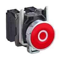
An Emergency Stop button, also known as an E-Stop, is for The person using the machinery and is a fail-safe control switch that provides safety both for the machinery. The Purpose of the emergency Push Button is to Stop the Machinery quickly when there is a risk of injury or the Workflow Requires Stopping. All Machinery Requires an Emergency Stop button to Reduce Risk. Buttons are typically red, Often With a Yellow Background to Ensure a Vivid and Easily Identified Solution.
Thank You for visiting the website. Keep visiting for more Updates.
Frequently asked questions
First, we need to connect the DP MCB with a power source, then connect the contactor with the DP MCB, and then connect the push switch and single-phase motor with the contactor. Now this circuit is ready for use.
Use a dial to easily set short and long times. Timing is not affected by voltage fluctuations or temperature changes, and the elapsed time could be easily read from a moving pointer.
This motor is similar to the three-phase motor except that it has only two windings (a-a′ and b-b′) on its stator displaced 90° from each other. The a-a′ winding is connected directly to the single-phase supply.
Without a capacitor, a single-phase motor cannot produce the necessary phase shift and will not start. When power is supplied to a single-phase motor, the current in the stator winding creates a magnetic field that oscillates back and forth, but it does not rotate.
A startup winding, also known as the auxiliary winding, was used to create the torque needed to start the single-phase induction motor.
Read more Single Phase Wiring
What is a kilowatt-hour (kWh) | kwh formula | What does kwh mean
Introduction to Electrical Units and CircuitskW and kWh on your electricity bill As your home uses electricity during...
What is the Difference Between kVA | What does KVA mean | kVA formula
Difference Between KVA ExplainedWhat does KVA Mean? There are technical terms aplenty when it comes to generators, and...
Power Factor | Power Unit | Energy | Electricity Unit
Power factor definition | Calculating Power FactorPower Factor Values In a purely resistive circuit, the power factor...
0 Comments