3-Phase Motor Contactor Wiring Diagram:
This diagram shows how to make 3 Phase Motor Contactor Wiring Diagram. In this circuit, we use a TP MCB ( Tripple Pole Miniature Circuit Breaker ), a TP MCCB ( Tripple Pole Molded Case Circuit Breaker ), a DP MCB ( Double Pole Miniature Circuit Breaker ), an ammeter, a selector switch, a magnetic contactor, and a three-phase motor. This circuit is very simple and easy to make. If you want to know more about this circuit please stay check our youtube video for clear details.
Advertisements
3 Phase Motor Contactor Wiring Diagram:

Components needed For this Project:
You can get the components from any of the sites below:
- 3 Phase Motor (5 HP) [See Buy Click Amazon]
- TP MCB 40A [See Buy Click Amazon]
- MCCB 63A [See Buy Click Amazon]
- DP MCB 25A [See Buy Click Amazon]
- Single Phase Amperemeter [See Buy Click Amazon]
- Selector Switch (220V AC) [See Buy Click Amazon]
- Magnetic Contactor 40A [See Buy Click Amazon]
*Please note: These are affiliate links. I may make a commission if you buy the components through these links. I would appreciate your support in this way!
Advertisements
Components used to make the 3 Phase Motor Contactor Wiring:
01. 3 Phase Motor:

A 3-phase electric motor uses a 3-phase Power Supply to Convert Electric Energy into Mechanical Energy. It contains four Wires (Three hot Wires and one Neutral Wire) and Uses 3 Alternating Currents of the Same Frequency. Since it Generates a Rotating Magnetic Field, it does not need a Capacitor for the Startup. Some 3-phase Motors are Reversible, Which Means they can serve as Generators by Turning Mechanical Energy into Electrical Energy.
02. TP MCB:
The full meaning of MCB is Miniature Circuit Breaker for TP MCB. MCB is an electromagnetic switch or device. If for any reason a short circuit occurs in the supply line or load line (line to line or line to neutral) or in case of overload MCB. the MCB automatically trips and disconnects the main line circuit or household power supply Connection. TP MCB In 3 Pole MCB, Switching & Protection is affected in only 3-Phases and the Neutral is not part of the MCB. 3 pole MCB signifies the Connection of Three Wires for a 3-Phase system Red-Yellow-Blue Phase. 3-Phase Supply Only Without Neutral.

03. MCCB:
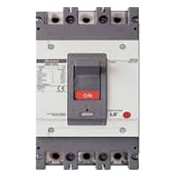
The MCCB consists of a bimetallic sheet that expands and contracts when the temperature of the MCCB changes. Due to overload, the bimetallic strip will start to bend and eventually. it will trip if more current flows in the circuit than the predetermined current. The trip mechanism opens the breaker. MCCB stands for Molded Case Circuit Breaker. It is another type of electrical protection device that is used when the load current exceeds the limit of a miniature circuit breaker. The MCCB provides Protection against Overload, and Short Circuit Faults and is also used for Switching the Circuits.
04. DP MCB:
DP MCB In 2 Pole MCB, switching & protection is affected in phases and the neutral. A Double Pole or DP Switch is a Switch that Controls 2 Circuits at the same time. In terms of Residential Switching, this Normally means it Switches the live and Neutral at the same time. In Layperson Terms, Double Pole switches or DP Switches are Exclusively Designed to Control 2 Different Electrical Circuits at the same time, which allows the Appliances to Isolate safely and reliably. Fan or light Combinations and Medical Equipment are some of the many applications for DP Electrical Switches and Electrical components.

05. Ammeter:

Ammeter, an instrument, with the help of which the flow of electricity can be measured directly in Electrical units, amperes. It is a galvanometer with very low resistance. As a result, the entire current flows through the meter coil. Current is measured with an ammeter. So it can be said that the device that measures the flow of current in an ampere unit is an ammeter. Electric current is the flow of electrons whose unit is an ammeter. So it can be said that the device that measures the flow of current in an ampere unit is an ammeter. An ideal ammeter has no internal resistance. But in reality. the ammeter has little internal resistance. The range of the ammeter depends on this resistance.
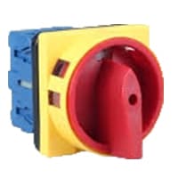
06. Selector Switch:
A Mechanical Switch That can be rotated Left, right, or center to open or close the Electrical contacts is known as a Selector switch. The Main Function of This Selector Switch is to Control Devices and also to Switch Between a Minimum of 2 or Above Electrical Circuits. The Perfect Used for Selector Switch is When Used for Controlling the Output of a Device. We know that a Selector switch is Used to control the electrical current flow in a Circuit it can also be used to both Initiate and inhibit the Current Flow.
07. Magnetic Contactor:

A magnetic contactor is an electromagnetic switching device. It is generally used for controlling 3-phase Motors. The operation of a magnetic contactor is similar to that of a Relay. but a relay is used for low-power or low-voltage connections, and a magnetic contactor is used for high-power or high-voltage connections. As soon as the supply is applied to the magnetic contactor coil. its normally open contacts are closed and normally closed contacts are opened and the associated devices are also operated. This is how a magnetic contactor works.
Thank You for visiting the website. Keep visiting for more Updates.
Frequently asked questions
Motor contactors work by controlling the circuit diagram to connect or disconnect the load from the power supply. This is done by energizing the coil which in turn closes the power supply contacts to supply power to the load or de-energizing the coil which opens the contact and disconnects the power supply to the load.
Perhaps the most common industrial use for the contactors was the control of electric motors. The top three contacts switch the respective phases of the incoming three-phase AC power, typically at least 480 V for motors 1 horsepower supply or greater.
Ensure the Motor is unloaded and the Variac is set at zero position. 3. Switch on the three-phase A.C. supply power and gradually increase the voltage through variac till its rated value. Thus the Motor was running at rated speed under NO LOAD condition.
Phase to Earth Resistance: Take the insulation tester, using the same setting, and check each lead from the phase to the frame of the motor. The minimum value of the insulation resistance should be 1 megohm. If the value is less than 0.2 megohms, replace the motor.
Standard three-phase motors can be connected with the star or delta method. 3-Phase Multi-Speed Motors: Multi-speed motors allow to work at different speeds for changing the magnetic poles without using any frequency converter electronic equipment.
Read more Single Phase Wiring
What is a kilowatt-hour (kWh) | kwh formula | What does kwh mean
Introduction to Electrical Units and CircuitskW and kWh on your electricity bill As your home uses electricity during...
What is the Difference Between kVA | What does KVA mean | kVA formula
Difference Between KVA ExplainedWhat does KVA Mean? There are technical terms aplenty when it comes to generators, and...
Power Factor | Power Unit | Energy | Electricity Unit
Power factor definition | Calculating Power FactorPower Factor Values In a purely resistive circuit, the power factor...
0 Comments