Solar Panel Hybrid Inverter Wiring
Learn how to wire a solar panel to a hybrid inverter with battery and home loads for efficient DC/AC power management and backup energy supply.

solar panel hybrid inverter wiring:
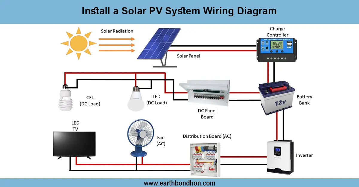
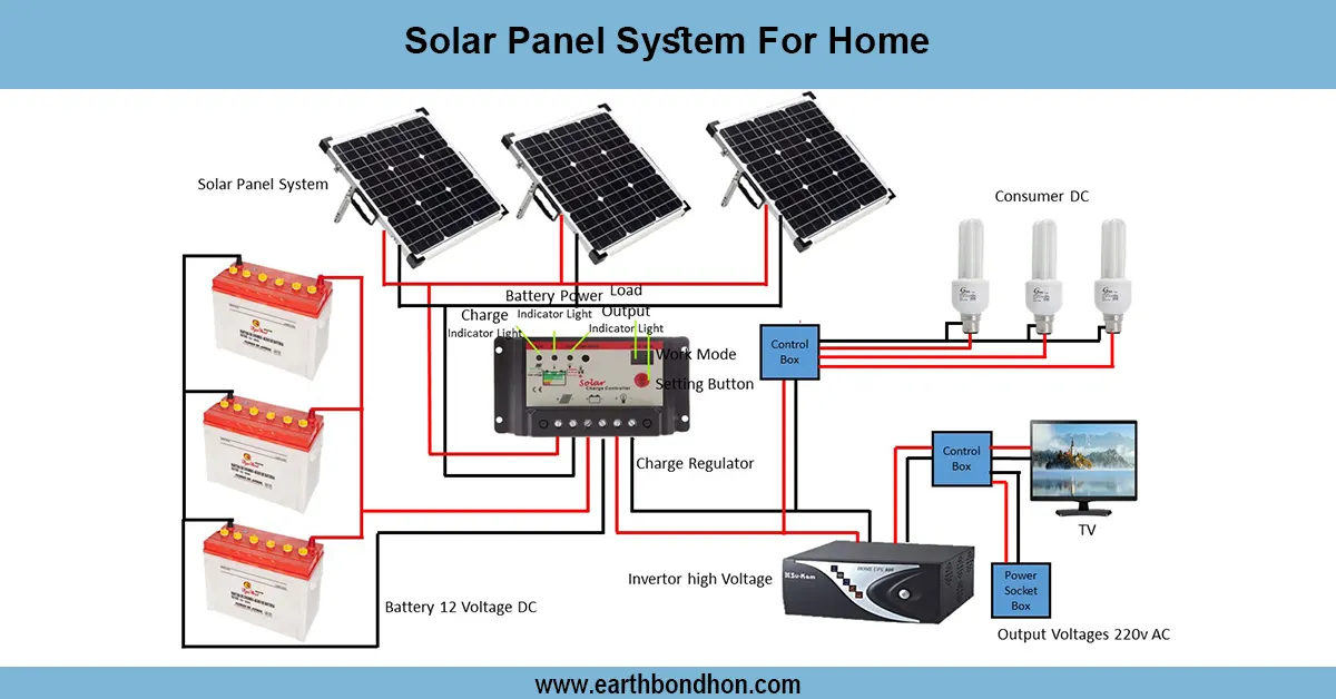
This solar panel hybrid inverter wiring diagram demonstrates how batteries are charged through the use of solar energy, as the AC loads run on the power of the solar energy. It combines the input of solar and battery, and the grid to maintain electricity and manage the energy efficiently.
home solar hybrid inverter diagram:
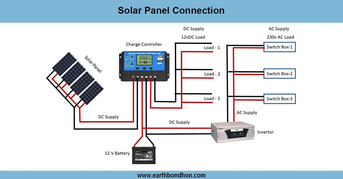
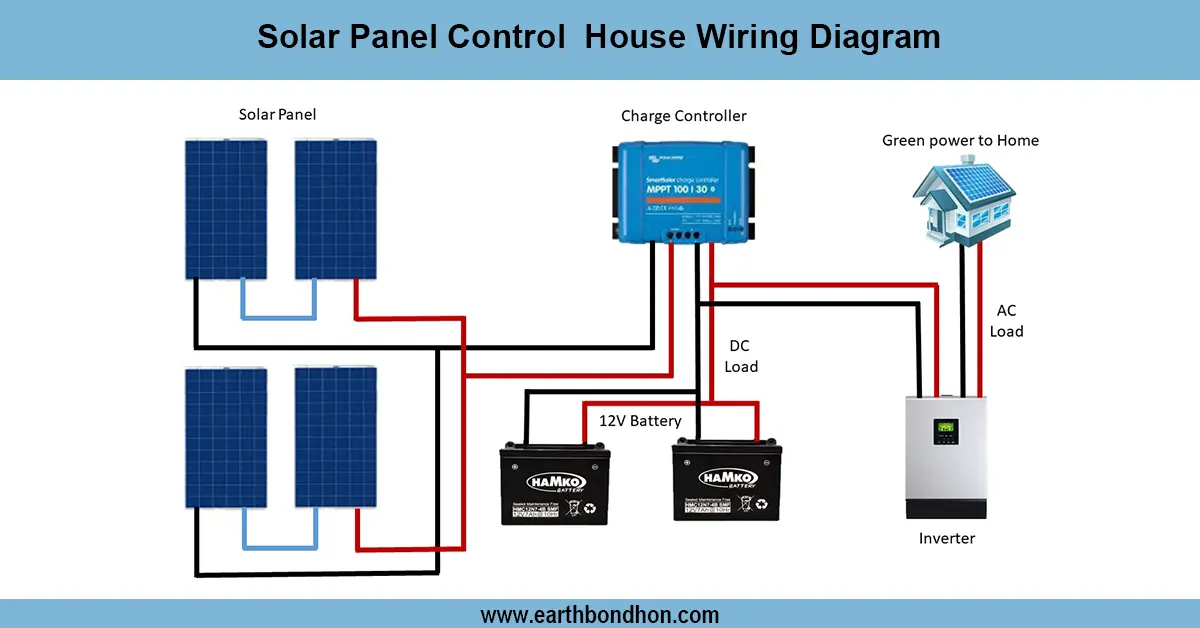
A solar panel in a hybrid inverter wiring diagram indicates the manner in which solar panels, batteries, and household loads can be incorporated effectively. A hybrid inverter can use solar energy and grid/generator input to power AC loads and charge batteries. The solar panels produce DC power, which is fed into the solar input of the hybrid inverter. The inverter is used to control power to charge the batteries safely and to power connected AC loads. The hybrid inverter can also pull power from the grid or generator during low sunlight or at night in order to sustain power. Correct wiring provides proper polarity as well as safety fuses or breakers. The DC loads may also be attached to the battery output directly in case of necessity. Hybrid inverter systems are suitable in a home or office where an uninterrupted power supply, maximizing the use of solar, and battery backup are required. Depending on the requirements of voltage and current, series or parallel connections may be applied to panels.
⚡ Work & Installation (Input → Output):
- Input: Solar panel generates DC power
- Step 1: Panels connected to hybrid inverter solar input
- Step 2: Inverter charges battery and powers AC load simultaneously
- Step 3: Battery stores energy for night or low sunlight
- Step 3: Hybrid inverter draws from grid/generator if solar/battery insufficient
- Output: Continuous AC/DC power supply for home or office loads
Testing & Final Adjustments:
Connect the solar panel to the hybrid inverter. First, ensure that all DC connections (solar panel and battery) are correct in their polarity. Confirm that the inverter has started and it is sensing the input from the sun. Monitor battery charging current and voltage during daylight to verify that it is operating properly. Plug AC loads and ensure that they are powered by solar first, a nd verify inverter display or LEDs that it is the correct state. Back-up test battery: Turn off the solar input, and watch whether the inverter draws power via battery or the power grid. Check all fuses and circuit breakers, and also verify that all cables used in the system are of the right size. Customize inverter functions, including battery voltage limits, charging current, and grid priority, based on the instructions. Observation over 24 hours to ensure smooth switching between the grid battery and solar input. Effective testing means safety, efficiency, and constant power.
Frequently Asked Questions - Solar Panel Hybrid Inverter Wiring:
What is a hybrid inverter?
A hybrid inverter combines solar input, battery storage, and grid or generator power to supply AC loads efficiently.
How do I connect solar panels to a hybrid inverter?
Connect the solar panel positive and negative to the solar input terminals of the hybrid inverter.
Do I need a battery with a hybrid inverter?
Yes, the battery stores solar energy for nighttime or backup usage.
Can I connect AC loads directly?
Yes, the hybrid inverter supplies AC loads directly from solar, battery, or grid input.
What voltage solar panels can be used?
12V, 24V, or 48V panels depending on the hybrid inverter specifications.
Do I need fuses or breakers?
Yes, for all DC and AC connections to ensure safety and prevent damage.
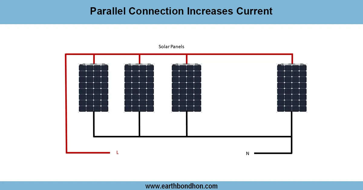
Can I connect multiple solar panels?
Yes, connect in series to increase voltage or parallel to increase current as required.
How do I test the hybrid inverter system?
Check DC voltage, battery charging current, AC output voltage, and system switching between solar and grid.
Does it work during grid failure?
Yes, the hybrid inverter can supply loads from the battery during grid outages.
Is this system suitable for homes?
Yes, ideal for homes or offices needing uninterrupted power and solar backup.