SSR Connection With Sensor Wiring Diagram:
This diagram shows how to make SSR Connection With Sensor Wiring Diagram. In this circuit, we use a 3-phase meter, a TP MCB ( Tripple Pole Minature Circuit Breaker ), an RCBO ( Residual Current Breaker with Over-Current ), 3 phase SSR, a rotary switch, and a 3-phase motor. This circuit is very simple and easy to make. If you want to know more details about this circuit please check our youtube video below the post and stay with us for more updates.
Advertisements
Diagram of SSR Connection With Sensor Wiring:

Components needed For this Project:
You can get the components from any of the sites below:
- Three Phase Energy Meter [See Buy Click Amazon]
- TP RCBO 32A [See Buy Click Amazon]
- FT MCB 40A [See Buy Click Amazon]
- Selector Switch (220V AC) [See Buy Click Amazon]
- 3 Phase Motor (5 HP) [See Buy Click Amazon]
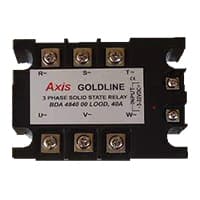
- 3 phase SSR [See Buy Click Amazon]
*Please note: These are affiliate links. I may make a commission if you buy the components through these links. I would appreciate your support in this way!
Advertisements
Components used to make the SSR Connection With Sensor Wiring:
01. 3 Phase Energy Meter:
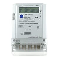
The Meter Which is used for Measuring the Power of the 3-phase supply is known as the 3-phase energy meter. A 3-phase Energy meter is a 3-phase 4-wire direct Connected meter that is Used to estimate the electricity on the Three-phase power supply, mostly for residential & commercial use. A 3-phase meter helps consumers & utilities in revenue protection. The 3-phase meter is Constructed by Connecting the 2 single-phase meters through the shaft.
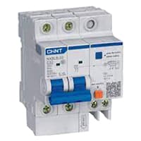
02. RCBO:
An RCBO protects Electrical equipment against 2 types of faults. Residual current and over current. Residual current. or earth leakage as it is sometimes referred to, occurs when there is a break in the circuit which can be caused by faulty electrical wiring or if the wire is accidentally cut. When there is a break in the circuit which may be due to faulty electrical wiring or accidental cutting of the wire. To prevent the current from being redirected and causing an electric shock. the RCBO current breaker stops it.
03. FP MCB:
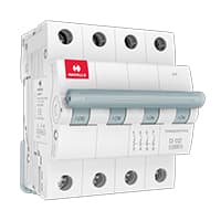
4 pole MCB for 4-Wires Connections, the one additional 4th pole for Neutral Wire Connection so that between Neutral and any of the other three will supply. In 4-Pole MCB the Neutral Pole is also having Protective release as in the Phase Poles connection. 3 Phase Supply with Neutral. TPN means triple pole TP + Neutral which is 3 - phases and Neutral. but the Protection is given for 3 Phases only and in 4 poles MCB Protection is given to all 3-Phases as well as Neutral. In the case of a 4-pole MCB. A Purpose is not to protect the Neutral but it is rather to Isolate the Neutral.
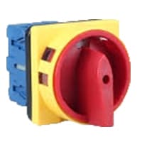
04. Rotary Switch:
A Mechanical Switch That can be rotated Left, right, or center to open or close the Electrical contacts is known as a Selector switch. The Main Function of This Selector Switch is to Control Devices and also to Switch Between a Minimum of 2 or Above Electrical Circuits. The Perfect Used for Selector Switch is When Used for Controlling the Output of a Device. We know that a Selector switch is Used to control the electrical current flow in a Circuit it can also be used to both Initiate and inhibit the Current Flow.
05. 3 Phase Motor:

A 3-phase electric motor uses a 3-phase Power Supply to Convert Electric Energy into Mechanical Energy. It contains four Wires (Three hot Wires and one Neutral Wire) and Uses 3 Alternating Currents of the Same Frequency. Since it Generates a Rotating Magnetic Field, it does not need a Capacitor for the Startup. Some 3-phase Motors are Reversible, Which Means they can serve as Generators by Turning Mechanical Energy into Electrical Energy.
06. 3 Phase SSR:
3 Phase Solid State Relay is a fully Integrated Device with a Heat sink and DIN rail Mounting plate in a Space-Saving design. Each unit is Touch-Safe with LED input Indication. This Normally Open, Zero-Crossing device is Capable of Millions of Cycles of Operation. There are three main types of solid-state relay isolation methods used in SSRs, i.e., optical, Transformer, and reed Solid-state relays are the semiconductor equivalents of electromechanical relays and therefore can be used to control Electrical loads.
Thank You for visiting the website. Keep visiting for more Updates.
Frequently asked questions
A Solid State of the Relay (SSR) is a relay that does not have a moving contact. In terms of operation, SSRs are not very different from mechanical relays that have moved to the contacts. SSRs, however, employ semiconductor switching elements, such as thyristors, diodes, and transistors. Structure or Operating Principle.
Solid state relay switches could be classified into three different types or "forms", based on the pole or throw information above. Form A switches are SPST (single pole, single throw) or normally open (NO). Form B switches are SPST or normally closed (NC).
One of the main components of a solid state of the relay (SSR) is an opto-isolator (also called an optocoupler) that contains one (or more) infra-red light-emitting diode, or LED light source or a photo-sensitive device within a single case. The optoisolator isolates the input of the output.
Solid state relays could be designed to operate either based on AC or DC input currents supply, depending on the specific model and applications. Common voltages for DC input include 5V, 12V, and 24V DC solid state relays, while widely available examples of AC solid state relays are often based around 120V or 240V AC input.
Server-side rendering (SSR) could be a powerful tool for improving the performance and user experience of web applications. By rendering HTML on the server before sending it to the client, SSR could significantly reduce the time required to display a web page, resulting in faster load times and a better user experience.
Read more Single Phase Wiring
What is a kilowatt-hour (kWh) | kwh formula | What does kwh mean
Introduction to Electrical Units and CircuitskW and kWh on your electricity bill As your home uses electricity during...
What is the Difference Between kVA | What does KVA mean | kVA formula
Difference Between KVA ExplainedWhat does KVA Mean? There are technical terms aplenty when it comes to generators, and...
Power Factor | Power Unit | Energy | Electricity Unit
Power factor definition | Calculating Power FactorPower Factor Values In a purely resistive circuit, the power factor...
0 Comments