Submersible Motor Control Box Wiring:
This diagram shows how to make submersible motor control box wiring. In this circuit, we use a main switch, a DPST switch ( Double Pole Single Throw ), an overload protector, a capacitor, and a submersible pump. First, we need to input power to the Main switch, then input the line to the DPST switch and overload like this diagram. Then we need to input connected to the motor and capacitor is like our circuit diagram. If you want to know more about this circuit please check our youtube video below the post.
Advertisements
Diagram of Submersible Motor Control Box Wiring:

Components needed For this Project:
You can get the components from any of the sites below:
- Main Switch [See Buy Click Amazon]
- DPST Switch [See Buy Click Amazon]
- Refrigerator Overload [See Buy Click Amazon]
- 50 MFD Capacitor (220V ac Line) [See Buy Click Amazon]
- single phase Submersible water pump (1 HP) [See Buy Click Amazon]
*Please note: These are affiliate links. I may make a commission if you buy the components through these links. I would appreciate your support in this way!
Advertisements
Components used to make the Submersible Motor Control Box Wiring:
01. Main Switch:
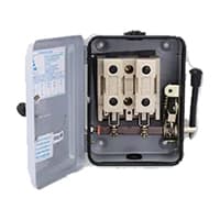
The Main Switch is Connected to the live and Neutral Wires. It is Used to Cut the Connections of the Live Wire as well as the Neutral Wire Simultaneously from the Main Supply. The main switch Isolates the Electrical supply from the whole installation so that it can be turned off for Servicing or Maintenance. It also provides overload protection for the mains cables (on newer switchboards) so that they will trip if the cable is Drawing too Much Power.
02. DPST Switch:
DPDT With two poles and two throws for each pole, the DPDT switch has six terminals — 2 inputs and four outputs (or 2 outputs for each individual circuit). A DPDT switch controls 2 separate circuits with the same actuator. which is generally designed for an on-on or on-off-on function. DPDT or Double pole, double throw switches will break or make the 2 conductors connected to 2 separate circuits. In this switch. DP switches control 2 independent circuits whereas DT switches close a circuit in the up & down position.

03. Overload Relay:

Overload Protection is Protection Against a Running Overcurrent That Would Cause Overheating of The Protected Equipment. Hence, An Overload is Also a Type of Overcurrent flow. Overload Protection Typically Operates on an Inverse Time curve where the Tripping Time Becomes less as the Current Increases. This Overload Protector is an Essential Component for Many Sockets Power Systems. The Top-Quality Overload Protector can Effectively Protect Electrical Products from Power Surges.
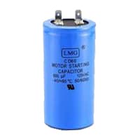
04. Capacitor:
Motor Starting Capacitors are used during the Motor Startup Phase and are Disconnected From the Circuit once the Rotor Reaches a Predetermined Speed, Which is Usually about 75% of the Maximum Speed for that Motor type. These Capacitor Usually Have Capacitance Values Of Over 70 UF. The Starting capacitor creates a Current-to-Voltage lag in the Separate start Windings of the Motor. Starting Capacitor are Wired into The Auxiliary Winding Circuit of the Motor and are Disconnected from the main winding circuit by the Centrifugal Switch once the Motor has Reached a Predetermined Speed.
05. Submersible Pump:
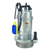
A Submersible Pump Is an Air-Tight Sealed Motor Close-Coupled to The pump is body. The Main Advantage of This Type of Pump is That it Prevents Pump Cavitation, a Problem Associated With a High Elevation Difference Between the submersible Pump and the Fluid Surface. Submersible Pumps As The Name Suggests Are made To Be fully Submerged in Water. It is a Centrifugal Water Pump, Meaning It Has a Motor That Powers An impeller Designed to Rotate And Push Water Outwards. The Motor is located Within a Waterproof Seal and is Closely Coupled to The body of The Pump That it Powers.
Thank You for visiting the website. Keep visiting for more Updates.
Frequently asked questions
The single-phase Rainbow-PS Submersible Motor (LRS-10H) requires an ideal power supply of 180 to 230 V. Power supply fluctuations can cause severe damage to all electrical appliances, including the motor. Always ensure that the submersible motor remains completely submerged in water.
A power level of 1 hp in submersible water pumps is approximately equivalent to 746 watts (W) or 0.746 kilowatts (kW). This results in higher performance of the pumps.
In a three-wire well pump configuration, the motor is connected by a black, red, yellow, or green (ground) wire. 3-wire pumps utilize a separate control box outside the motor that houses the important starting components, which are usually mounted on a nearby wall above the ground.
It requires a voltage of 250-440 V, single-phase, and comes with a CE mark. The Crompton one-3 HP Submersible Pump is a single-phase, vertical shaft, single suction type water motor used for irrigation of fields, gardens, or domestic purposes.
As submersible pumps are fully submerged, the pressure of the water surrounding them prevents air from being trapped. As a result, all submersible pumps are self-priming. The water surrounding the pump helps to keep it cool and prevents overheating.
Read more Single Phase Wiring
What is a kilowatt-hour (kWh) | kwh formula | What does kwh mean
Introduction to Electrical Units and CircuitskW and kWh on your electricity bill As your home uses electricity during...
What is the Difference Between kVA | What does KVA mean | kVA formula
Difference Between KVA ExplainedWhat does KVA Mean? There are technical terms aplenty when it comes to generators, and...
Power Factor | Power Unit | Energy | Electricity Unit
Power factor definition | Calculating Power FactorPower Factor Values In a purely resistive circuit, the power factor...
0 Comments