Air Cooler Wiring Diagram:
This diagram shows how to make Air Cooler Wiring Diagram. In this circuit, we use an air cooler, a 2-pin plug, a motor dimmer, 2 switches, an indicator light, and a pump motor. First, we need to input the phase line to the switch, dimmer, pump motor, and air cooler motor, then need to input the neutral and dimmer connection to the motor. Now this circuit is ready for use. If you want to know more about this circuit please check our youtube video below the post.
Advertisements
Diagram of Air Cooler Wiring Diagram:

Components needed For this Project:
You can get the components from any of the sites below:
- Air Cooler [See Buy Click Amazon]
- single phase Mini Motor[See Buy Click Amazon]
- 2 Pin Plug 220V AC [See Buy Click Amazon]
- Gang Dimmer [See Buy Click Amazon]
- SPST Switch [See Buy Click Amazon]
- Indicator Light 220v AC [See Buy Click Amazon]
*Please note: These are affiliate links. I may make a commission if you buy the components through these links. I would appreciate your support in this way!
Advertisements
Components used to make the Air Cooler Wiring Diagram:
01. Air Cooler:

Air Coolers Are Also Known as Evaporative or Purified Coolers, And it Cools The Atmosphere By Evaporating Water. When Air Flows Through Water. Some Particles On The Water is Surface Will Be Blown Away. These Particles Carry Heat With Them And Cool The Air. This Is The Main Mechanism Behind the Air cooler system. Air Coolers Work on The Evaporative Cooling Principle working. Where Water Evaporation Is Used To Cool The Air. When The Sweat Begins to Evaporate. it Draws Out Excess Heat Absorbed by The skin in The Form of Gas which Results in Cold in The Case of cold Weather.
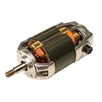
02. Motor:
A universal motor is a type of electric motor that can be powered by either AC or DC power and uses an electromagnet as its stator to generate a magnetic field. It is a commutated series wound motor, with the stator field coils connected in series with the rotor windings through a commutator. The universal Motor is structurally very similar to a DC series motor but slightly modified to operate with AC power. This type of electric motor is well operated by AC because the field on both sides can be varied in conjunction with the current flowing through the coil and armature.
03. Motor Dimmer:
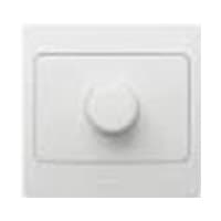
A Fan Speed Controller Controls The Voltage Across the Fan and Therefore Indirectly Controls its speed 220v AC line. A ceiling Fan Speed Regulator Actually Measures and Regulates the Speed of the Fan Using its Tachometer. Fan Speed is Controlled with Thyristor or Transformer Speed Controllers for Ceiling fans, and table fans. the fan is Controlled by a Capacitor, and the Voltage across the fan Determines the fan speed. A Speed Control loop Can be Implemented That is Independent of Manufacturing Variances and Wear on The Fan control system.
04. Switch:
An SPST (Single Pole Single Throw) Switch is a Switch That only Has a Single Input and can Connect Only to one Output. This means it Only Has one Input Terminal and Only 1 Output Terminal. A Switch is a Mechanical or Controlling Device That Changes the Flow of Current Direction or Interrupts the Flow of Current Within a Circuit diagram. An electrical line using Single Pole Single Throws (SPST) is Perfect for on-off switching. When the SPST is closed, the Circuit is Closed and the light from the lamp switches on the system. When The Single Pole Single Throw (SPST) is then opened, the light from the lamp goes out and the Circuit is off.

05. Indicator:

An indicator lamp just Sounds Technical, Sometimes it is called a Supervisory light Indicator. Indicator lights are amber in color and can be located at the Front, the Rear, and Sometimes at the Side of the car on both the left And Right-hand sides. The Common colors used by Indicator lamps are red, yellow, blue, white, and green line system. A Panel Indicator Lamp Generally has up to 5 Differently Colored Segments to Indicate Various Conditions on the Machine or Process system.
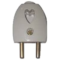
06. 2-Plug:
2-Pole Means That the Device Plug is not Earthed and it Normally Has 2-Pins That Transmit Electricity. Originally, all Electrical Devices were Fitted with 2-pole Plugs, Which Means that the Devices were not earthed and that all main Sockets were Constructed for 2-pole plugs system. 2-pin Plugs Consist of 2 flat or Round Pins with one Called “hot” “live” or "line" and the Other Called “neutral”. When Connected to an Electric Circuit, the Current Flows From the live Pins Through The Copper Conductor and into the Device system.
Thank You for visiting the website. Keep visiting for more Updates.
Frequently asked questions
Air coolers work on the principle of an evaporative cooling system. The basic idea is to use a fan to circulate air over a wet surface, causing evaporation of the water or cooling the air. The air cooler uses a fan to blow hot the air over a wet evaporative pad.
The protective ground is green and green with a yellow stripe. The neutral is white, the hot (live and active) single-phase wires are black, and red in the case of a second active. The 3-phase lines are red, black, and blue.
On the cooler side, the black wire connects to the blower pump via a junction. The other end of the black to the wire is connected to the switch. The white wires and neutral connect to the common junction point on the water motor and the white connection point on the switch.
We advise that you refill your personal cooler after it operates for an approximate period of four to six hours. Between 2 to 6 months, you could perhaps replace the pad cartridge.
Air coolers are also known as evaporative or purified coolers, and they cool the atmosphere by evaporating water. When air flows through water, some particles on the water's surface will be blown away. These particles carry heat with them or cool the air. This is the main mechanism of the behind air coolers.
Read more Single Phase Wiring
What is a kilowatt-hour (kWh) | kwh formula | What does kwh mean
Introduction to Electrical Units and CircuitskW and kWh on your electricity bill As your home uses electricity during...
What is the Difference Between kVA | What does KVA mean | kVA formula
Difference Between KVA ExplainedWhat does KVA Mean? There are technical terms aplenty when it comes to generators, and...
Power Factor | Power Unit | Energy | Electricity Unit
Power factor definition | Calculating Power FactorPower Factor Values In a purely resistive circuit, the power factor...
0 Comments