Interfacing 16×2 LCD
LCDs (Liquid Crystal Displays) area unit utilized in embedded system applications for displaying numerous parameters and standing of the system.
LCD sixteenx2 may be a 16-pin device that has a pair of rows that may accommodate 16 characters every.
LCD 16×2 is utilized in 4-bit mode or 8-bit mode.
It is additionally potential to form custom characters.
It has eight knowledge lines and three management lines that may be used for management functions.
For additional info concerning liquid crystal display 16×2 and the way to use it, refer the subject liquid crystal display 16×2 module within the sensors and modules section.

The name and functions of each pin of the 16×2 LCD module is given below.
16×2 LCD Module Pin Out Diagram
The JHD162A liquid crystal display module has sixteen pins and might be operated in 4-bit mode or 8-bit mode. Here we tend to ar mistreatment the liquid crystal display module in 4-bit mode. Before going into the small print of the project, let’s have a glance at the JHD162A liquid crystal display module. The schematic of a JHD162A liquid crystal display pin diagram is given below.
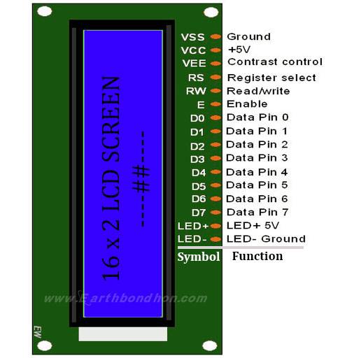
Pin1(Vss): Ground pin of the liquid crystal display module.
Pin2(Vcc): Power to the liquid crystal display module (+5V provide is given to the present pin)
Pin3(VEE): distinction adjustment pin. this is often done by connecting the ends of a 10K potentiometer to +5V and ground and so connecting the slider pin to the VEE pin. The voltage at the VEE pin defines the distinction. the traditional setting is between zero.4 and 0.9V.
Pin4(RS): Register chooses a pin. The JHD162A has 2 registers specifically command register and information register. Logic HIGH at RS pin selects information register and logic LOW at RS pin selects command register. If we tend to create the RS pin HIGH and feed input to the info lines (DB0 to DB7), this input is going to be treated as information to show on the liquid crystal display screen. If we tend to create the RS pin LOW and feed input to the info lines, then this may be treated as a command ( a command to be written to liquid crystal display controller – like positioning the pointer or clear screen or scroll).
Pin5(R/W): Read/Write modes. This pin is employed for choosing between reading and write modes. Logic HIGH at this pin activates scan mode and logic LOW at this pin activates write mode.
Pin6(E): This pin is supposed for enabling the liquid crystal display module. A HIGH to the LOW signal at this pin can alter the module.
Pin7(DB0) to Pin14(DB7): These are information pins. The commands and information are fed to the liquid crystal display module through these pins.
Pin15(LED+): Anode of the backlight junction rectifier. once operated on 5V, a 560-ohm electrical device ought to be connected nonparallel to the present pin. In Arduino primarily based comes the backlight junction rectifier is often power-driven from the three.3V supply on the Arduino board.
Pin16(LED-): Cathode of the backlight junction rectifier.
| Pin No: | Name | Function |
| 1 | VSS | This pin must be connected to the ground |
| 2 | VCC | Positive supply voltage pin (5V DC) |
| 3 | VEE | Contrast adjustment |
| 4 | RS | Register selection |
| 5 | R/W | Read or write |
| 6 | E | Enable |
| 7 | DB0 | Data |
| 8 | DB1 | Data |
| 9 | DB2 | Data |
| 10 | DB3 | Data |
| 11 | DB4 | Data |
| 12 | DB5 | Data |
| 13 | DB6 | Data |
| 14 | DB7 | Data |
| 15 | LED+ | Back light LED+ |
| 16 | LED- | Back light LED- |
Arduino IDE the program.
To facilitate communication between Arduino and LCD module, we make use of a built-in library in Arduino <LiquidCrystal.h> – which is written for LCD modules making use of the Hitachi HD44780 chipset (or a compatible chipset). This library can handle both 4-bit mode and 8-bit mode wiring of LCD.
Circuit Schematics
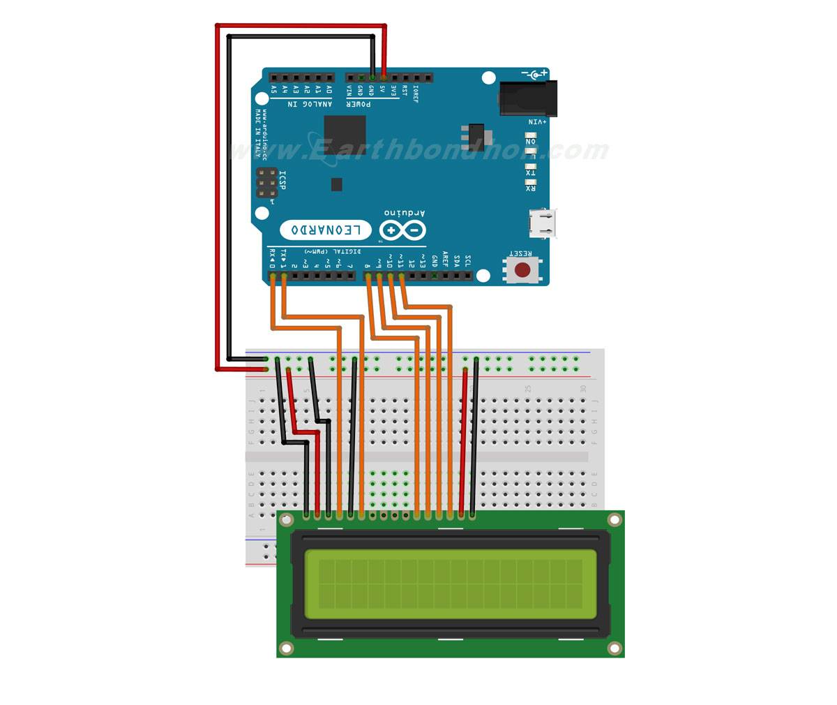
Components needed for this Project
- Arduino Uno : [ See Buy Click Banggood | Amazon ]
- 230 ohms and 470 ohms [ See Buy Click Banggood | Amazon ]
- 16X2 LCD Module [ See Buy Click Banggood | Amazon ]
- Jump Wires [ See Buy Click Banggood | Amazon ]
- Breadboard [ See Buy Click Banggood | Amazon ]
*Please note: These are affiliate links. I may make a commission if you buy the components through these links. I would appreciate your support in this way!
Im impressed, I need to say. Really hardly ever do I encounter a blog thats both educative and entertaining, and let me inform you, you have got hit the nail on the head. Your concept is outstanding; the difficulty is one thing that not sufficient individuals are talking intelligently about. I’m very glad that I stumbled throughout this in my seek for something regarding this.