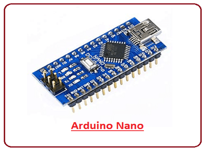
Arduino Nano Board
An Arduino Nano board, a quiet microcontroller board created by the Arduino team, is the subject of this article, which provides thorough information about it. Atmega168 or Atmega328p serve as the foundation for this microcontroller. It is quite similar to the Arduino Uno board, however, because of its smaller size, the Nano board has supplanted the Arduino Uno in terms of pin arrangement and capabilities. This board is similar to an Arduino Duemilanove board in many ways and features. It lacks a DC jack, so power is typically supplied through a tiny USB port that is otherwise directly linked to the pins for VCC and GND. Using a micro USB connector on the board, this board is frequently provided with 6 to 20 volts of power.
What is an Arduino Nano Board?
It is frequently constructed with an Atmega328 microcontroller. This particular microcontroller is also used in the Arduino UNO. It is a little board that is flexible and has a good type of application. Arduino Mega, Arduino Pro Mini, Arduino UNO, Arduino YUN, Arduino pad, Arduino Leonardo, and Arduino Due are the most common additional Arduino boards. This board is similar to an Arduino Duemilanove board in many ways and features. It lacks a DC jack, so power is typically supplied through a tiny USB port that is otherwise directly linked to the pins for VCC and GND. Using a micro USB connector on this board, 6 to 20 volts are frequently provided.
Features
- ATmega328P Microcontroller is from 8-bit AVR family
- Operating voltage is 5V
- Input voltage (Vin) is 7V to 12V
- Input/output Pins are 22
- Analog i/p pins are 6 from A0 to A5
- Digital pins are 14
- Power consumption is 19 mA
- I/O pins DC Current is 40 mA
- Flash memory is 32 KB
- SRAM is 2 KB
- EEPROM is 1 KB
- CLK speed is 16 MHz
- Size of the printed circuit board is 18 X 45mm, Weight-7g
- Supports three communications like SPI, IIC, & USART
Arduino Nano Pinout
Arduino nano pin configuration is shown below and each pin functionality is discussed below.
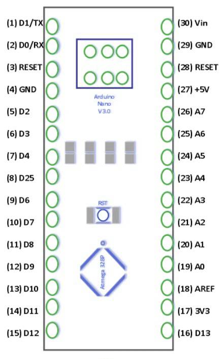
1. Power Pin: These pins are power pins (Vin, 3.3V, 5V, GND).
When an external power source between 7V and 12V is used, Vin, the board’s input voltage, is utilized.
The Nano board’s regulated power supply voltage is 5V, and it is utilized to provide power to the board and its components.
The voltage regulator on the PCB may provide a minimum value of 3V.
The board’s ground pin is labeled GND.
2. RST Pin (Reset): The microcontroller is reset via this pin.
3. Analog Pins (A0-A7): These pins are utilized to determine the board’s analog voltage between 0V and 5V.
4. I/O Pins (Digital Pins D0–D13): These pins are utilized as i/p pins unless they are designated as o/p pins. 0V & 5V
5. Serial Pins (Tx, Rx): TTL serial data is transmitted and received via these pins.
6. External Interrupts (2, 3): An interrupt is triggered by these pins.
7. PWM (3, 5, 6, 9, 11): These ports are used to produce PWM data in an 8-bit format.
8. SPI: SPI communication is supported through pins 10, 11, 12, and 13.
9. Internal LED (13): The LED is turned on using this pin.
10. The IIC pins (A4, A5) are used to support TWI communication.
11. AREF: This pin provides the input voltage with a reference voltage.
Applications
Here are a few of its applications but it has an extensive range which we can’t discuss here. So here’s the tip of the iceberg:
- Embedded Systems.
- Automation.
- Robotics.
- Control Systems.
- Instrumentation.