Dol Starter Circuit Diagram:
This diagram shows how to make a dol starter circuit diagram. In this circuit, we use TP MCB ( Tripple Pole Miniature Circuit Breaker ), a selector switch, a magnetic contactor, an overload, a voltage indicator meter, and a drilling machine. This circuit diagram is very simple and easy to make. If you want to know more clear details about this circuit please check our youtube video and stay with us.
Advertisements
Diagram of Dol Starter Circuit Diagram:

Components needed For this Project:
You can get the components from any of the sites below:
- TP MCB 40A [See Buy Click Amazon]
- Magnetic Contactor 40A [See Buy Click Amazon]
- single phase Volt Meter [See Buy Click Amazon]
- Selector Switch (220V AC) [See Buy Click Amazon]
- Motor Protector Overload [See Buy Click Amazon]
- Drilling Machine [See Buy Click Amazon]
*Please note: These are affiliate links. I may make a commission if you buy the components through these links. I would appreciate your support in this way!
Advertisements
Components used to make the Dol Starter Circuit Diagram:
01. TP MCCB:
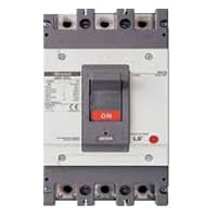
The MCCB consists of a bimetallic sheet that expands and contracts when the temperature of the MCCB changes. Due to overload, the bimetallic strip will start to bend and eventually. it will trip if more current flows in the circuit than the predetermined current. The trip mechanism opens the breaker. MCCB stands for Molded Case Circuit Breaker. It is another type of electrical protection device that is used when the load current exceeds the limit of a miniature circuit breaker. The MCCB provides Protection against Overload, and Short Circuit Faults and is also used for Switching the Circuits.
02. Magnetic Contactor:
A magnetic contactor is an electromagnetic switching device. It is generally used for controlling 3-phase Motors. The operation of a magnetic contactor is similar to that of a Relay. but a relay is used for low-power or low-voltage connections, and a magnetic contactor is used for high-power or high-voltage connections. As soon as the supply is applied to the magnetic contactor coil. its normally open contacts are closed and normally closed contacts are opened and the associated devices are also operated. This is how a magnetic contactor works.

03. Voltmeter:

An instrument that measures the potential difference between any two points in a circuit directly in volts is called a voltmeter. A voltmeter is an Electrical instrument that directly measures the potential difference between any 2 points in a circuit in volts. The voltmeter is connected in parallel with the 2 points in the circuit where the potential difference is to be measured. This instrument consists of a galvanometer. Like an electric cell or an ammeter, a voltmeter has 2 terminals, a positive and a negative terminal. Usually, the positive end is red and the negative end is black.
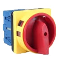
04. Selector Switch:
A Mechanical Switch That can be rotated Left, right, or center to open or close the Electrical contacts is known as a Selector switch. The Main Function of This Selector Switch is to Control Devices and also to Switch Between a Minimum of 2 or Above Electrical Circuits. The Perfect Used for Selector Switch is When Used for Controlling the Output of a Device. We know that a Selector switch is Used to control the electrical current flow in a Circuit it can also be used to both Initiate and inhibit the Current Flow.
05. Overload Relay:

Overload Protection is Protection Against a Running Overcurrent That Would Cause Overheating of The Protected Equipment. Hence, An Overload is Also a Type of Overcurrent flow. Overload Protection Typically Operates on an Inverse Time curve where the Tripping Time Becomes less as the Current Increases. This Overload Protector is an Essential Component for Many Sockets Power Systems. The Top-Quality Overload Protector can Effectively Protect Electrical Products from Power Surges.
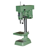
06. Drilling Machine:
A drilling Machine is a Powerful tool that is used to drill Cylindrical holes into various objects and materials. The Machine spins a tool bit at high speed by an Electric Motor to Create holes in the Workpiece. It can be used to drill holes into Materials such as Metal, and wood. A Drilling Machine Called a Drill Press, is Used to cut Holes into or Through Metal, or Other Materials. Drilling Machines use a Drilling Tool That Has Cutting Edges at its Point.
Thank You for visiting the website. Keep visiting for more Updates.
Frequently asked questions
The DOL comprises the circuit diagram breaker, overload relay, and an electromagnetic contactor. The contactor was controlled by independent start and stop push buttons with an auxiliary contactor contact connected across the start push button where the contactor was latched electrically any time the motor was operational.
The Direct on Line motor starter (DOL) is designed to switch a single or three-phase induction motor at a rated voltage. It comprises an enclosure in steel or plastic, a contactor, a start contact, link wires, and stop/start buttons.
MCB and DOL starters are both electrical devices used for protection and control, but they have different functions and applications. MCB stands for Miniature Circuit Breaker and is used for Circuit Program MCB is short circuit use and the doc is overload protection use.
Easy to understand and troubleshoot. It provides 100% torque at the time of starting. Only one set of cables was required from the starter to the motor. The motor was connected in the delta at motor terminals.
When there is a break in the conducting path of an electric circuit, it is called an open circuit. When there is an unwanted path of very low resistance in an electric circuit is called a short circuit. The resistance of an open circuit diagram was tending to infinity.
Read more Single Phase Wiring
What is a kilowatt-hour (kWh) | kwh formula | What does kwh mean
Introduction to Electrical Units and CircuitskW and kWh on your electricity bill As your home uses electricity during...
What is the Difference Between kVA | What does KVA mean | kVA formula
Difference Between KVA ExplainedWhat does KVA Mean? There are technical terms aplenty when it comes to generators, and...
Power Factor | Power Unit | Energy | Electricity Unit
Power factor definition | Calculating Power FactorPower Factor Values In a purely resistive circuit, the power factor...
0 Comments