3-Phase contactor wiring diagram
Detailed 3-phase contactor wiring diagram showing power and control circuit connections for reliable switching of 3 phase motors and loads.

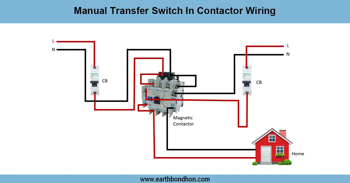
3 phase contactor wiring
The above 3-phase contactor wiring diagram demonstrates that power lines are connected to main contacts and control circuit wiring is connected to the coil, so that control over the 3-phase motors and any heavy loads can be achieved effectively.
3 Phase Contactor Wiring Summary:
Main Contacts: Connect three phase power lines (L1, L2, L3) to load
Coil Circuit: Energize coil via control switch or relay
Auxiliary Contacts: Used for control logic and feedback
Protection: Overload relay and circuit breaker integration
motor starter wiring
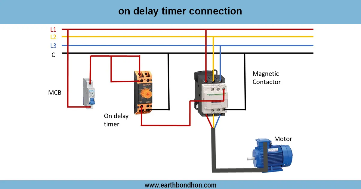
A 3 phase contactor is an electromechanical switch between power sources and motors/heavy electrical loads. Contactor wiring has two-part circuit The main contacts on the contactor are connected to a 3-phase power supply and the control coil circuit is wired to a switch or to some type of control. When the coil is energized it closes the main contacts and sends power to the motor. Start/stop buttons, overload relays, and auxiliary contacts are incorporated in control wiring to be safe. Electrical wiring installed correctly allows contactor to safely carry high current loads and the contractor will offer dependable means of starting and stopping motors in industrial and commercial use.
electrical contactor connections
| Component | Connection | Purpose |
|---|---|---|
| Power Supply (L1, L2, L3) | Connected to contactor main contacts | Supply power to motor or load |
| Contactor Coil (A1, A2) | Connected to control switch and power source | Energizes main contacts when activated |
| Start/Stop Switch | Controls coil energizing circuit | Allows manual control of motor operation |
| Overload Relay | Connected in series with coil circuit | Protects motor from overload conditions |
| Auxiliary Contacts | Used for control logic and signaling | Feedback and interlocking functions |
Frequently Asked Questions - 3-Phase contactor wiring diagram:
What is a 3 phase contactor?
An electromechanical switch used to control 3 phase power to motors or loads.
How is the contactor coil wired?
Connected to a control circuit with switches or relays to energize the coil.
What do the main contacts do?
They connect or disconnect the 3 phase power supply to the load.
What is the role of auxiliary contacts?
Used for control feedback and interlocking in motor circuits.
How does the overload relay protect the motor?
It trips the coil circuit to disconnect power during overload conditions.
Can a contactor control other loads besides motors?
Yes, contactors can switch any suitable electrical load.
What voltage is required for contactor coils?
Coil voltage varies, commonly 24V, 110V, or 230V AC/DC depending on application.
Is a starter required with a contactor?
Yes, starters include contactors with overload protection for motors.
Who should wire a 3 phase contactor?
Qualified electricians should install contactors to ensure safety.
Can contactors be used in automation systems?
Yes, contactors are commonly used in automated motor control circuits.