3-phase Motor Wiring Diagram
Learn 3 phase motor wiring with star-delta starter, protective relays, and correct power connections for safe motor operation in industrial applications.

star delta motor connection:
A 3-phase motor wiring diagram illustrates the right connections in order to operate the motor safely. It has a star-delta starter, protective relays, and optional PF correction to make sure that its performance is efficient and will not cause damage.
three phase induction motor:
A 3 phase motor wiring diagram is a description of the connection that can be made between a 3-phase supply and an induction motor with ease. It consists of star-delta starter connections in order to minimize starting current, overcurrent, overload, and fault protective relays, and appropriate grounding. The schematic here indicates that the supply enters the motor control panel via the incoming supply of the LT/HT lines, via MCB/MCCB, and star-delta starter contacts. It is possible to add capacitor banks to the PFI panels to enhance the power factor. Proper wiring will make the voltage across the three phases equal, the motors will be stable, and faults will be prevented. This system finds its application in industrial motors, pumps, compressors, and heavy machinery. After installation, it is useful to test to make sure the settings of the relays, rotation of the motor, and balance of the current are proper to operate efficiently and safely.
⚡ Work & Installation (Input → Output):
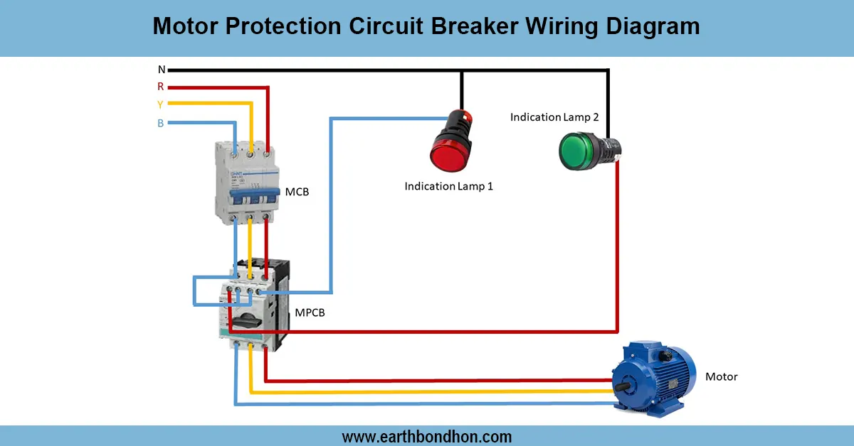
- 3 Phase Supply (HT/LT) enters the motor control panel.
- MCB/MCCB or circuit breaker protects against overcurrent.
- Star-Delta Starter connects to motor windings for reduced starting current.
- Protection Relays monitor overcurrent, earth fault, and overload.
- Motor Terminals receive the correct R, Y, B phase connections.
- Optional PFI Panel connects capacitor banks for power factor improvement.
- Motor runs safely with balanced voltage and correct rotation.
Testing & Final Adjustments:
- Check insulation resistance of motor windings before energizing.
- Verify correct phase sequence using phase sequence tester.
- Energize the motor in star mode, check starting current, then switch to delta mode for full operation.
- Test protective relays by simulating overload or earth fault conditions.
- Check PF values if capacitor banks are installed.
- Measure running current on all three phases to ensure balance.
- Confirm motor rotation direction is correct; swap two phases if needed.
- Adjust relay settings according to motor rating.
- Verify grounding continuity and cable connections.
- Record all test results for maintenance and future reference.
Frequently Asked Questions - 3-phase Motor Wiring Diagram:
What is a 3 phase motor wiring diagram?
It shows correct connections for motor operation, starter, and protection.
Why use star-delta starter?
To reduce starting current for 3 phase induction motors.
What protection devices are used?
Overcurrent relay, overload relay, earth fault relay, and circuit breakers.
Can motor run without star-delta starter?
Yes, but starting current will be high, risking damage.
How is power factor improved?
Using capacitor banks in a PFI panel connected parallel to the motor supply.
What is the correct phase sequence?
R-Y-B; incorrect sequence may reverse motor rotation.
What voltage is used for 3 phase motors?
Typically 400V line-to-line for LT motors, higher for HT motors.
How to check motor rotation direction?
Briefly energize and observe motor shaft; swap two phases if reversed.
Why test insulation resistance?
To prevent short circuits and ensure winding safety.
Can large motors use direct online starting?
Yes, but usually only for small motors due to high starting current.