


Motion Sensor Diagram
Learn PIR motion sensor wiring and connection diagram with step-by-step guide, working principle, installation tips, and testing for home and office lights.

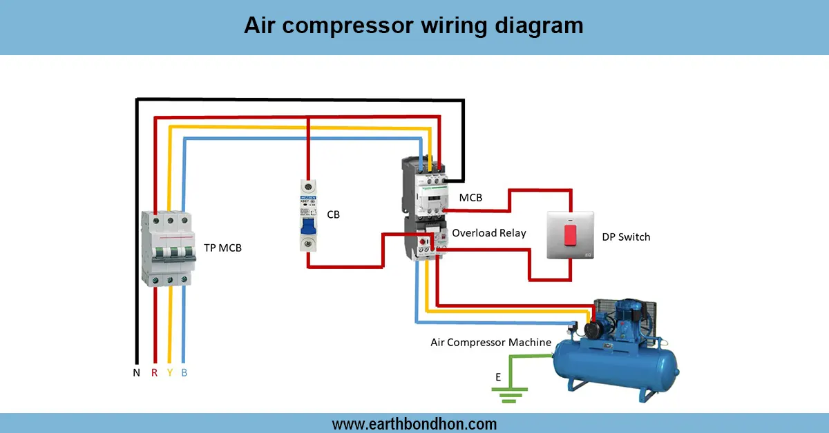
PIR motion sensor wiring diagram
PIR motion sensor wiring and connections have three terminals: live, neutral, and load. It also automatically turns ON the lamp when motion is sensed, and turns off after a predefined delay.
motion sensor wiring step by step
The wiring and connection system of a PIR motion sensor can be used to automatically control the lights or appliances when motion is detected. PIR (Passive Infrared) sensors pick up the infrared radiation produced by moving objects and transmit a signal to turn ON the attached load. The sensor normally consists of three terminals: Live (L), Neutral (N), and Load (Out). In the wiring, the phase (line) wire is connected to the sensor live, sensor neutral, and the load, the lamp phase terminal. Neutral of the lamp is connected directly to the supply. Such a design is popular in corridors, staircases, garages, gardens, and offices. Tune sensor settings such as sensitivity, delay time, and lux threshold to good effect. Safety is a matter of good insulation and fastenings.
Work / Installation (Inputs → Outputs)
- Input: Line (phase) and neutral from the supply.
- Output: Lamp or load connected through sensor.
steps:
- Connect line (phase) wire from supply to sensor L terminal.
- Connect neutral (N) from supply to sensor N terminal.
- Connect sensor load (Out) terminal to the phase terminal of the lamp.
- Connect the lamp neutral directly to supply neutral.
- Adjust sensitivity, time delay, and lux setting on the sensor.
- Power ON the circuit and test by moving in front of the sensor; the lamp should glow automatically.
Testing and Final Adjustments
Once the wiring is complete, make sure that all the terminals are tight and insulated. Make the power supply switch ON and check the sensor by passing in front of it. The lamp must turn on at once. Change time delay: The duration of time the lamp remains in the ON state when motion ceases. Change sensitivity to detect range and lux top to work at all day or only at night. Test at various angles and at various distances to get good detection. Latches. Fasten the sensor and lamp. A proper phase, neutral, and earth connection is always essential.
Frequently Asked Questions - Motion Sensor Diagram:
What is PIR motion sensor wiring?
It is the wiring connection of a PIR sensor to control a lamp or load automatically.
How many terminals does a PIR sensor have?
Three terminals: Live (L), Neutral (N), and Load (Out).
Where is a PIR sensor used?
In corridors, staircases, garages, gardens, and offices.
How is the sensor connected to a lamp?
Sensor load terminal connects to lamp phase; lamp neutral connects directly to supply.
Can the sensitivity of PIR sensor be adjusted?
Yes, most sensors have a knob to adjust detection sensitivity.
What is the time delay in PIR sensor?
It determines how long the lamp stays ON after motion stops.
Does PIR sensor work in daylight?
It can, but lux setting can limit operation to night only.
Is earthing required?
Yes, for safety, connect earth wire if available.
What happens if wiring is incorrect?
The lamp may not turn ON or may flicker; correct wiring is essential.
Can multiple lamps be connected to one PIR sensor?
Yes, if the sensor contact rating supports the total load.