Motor control from two places
Wiring diagram for using two-way switches to control a motor’s ON/OFF operation from two different locations safely and efficiently.

two way switch motor wiring
Wiring two way switches in motor circuits enables the motor to operate ON or OFF under two locations with traveling wires between switches that feed the motor switch.
Formula & Table Summary:
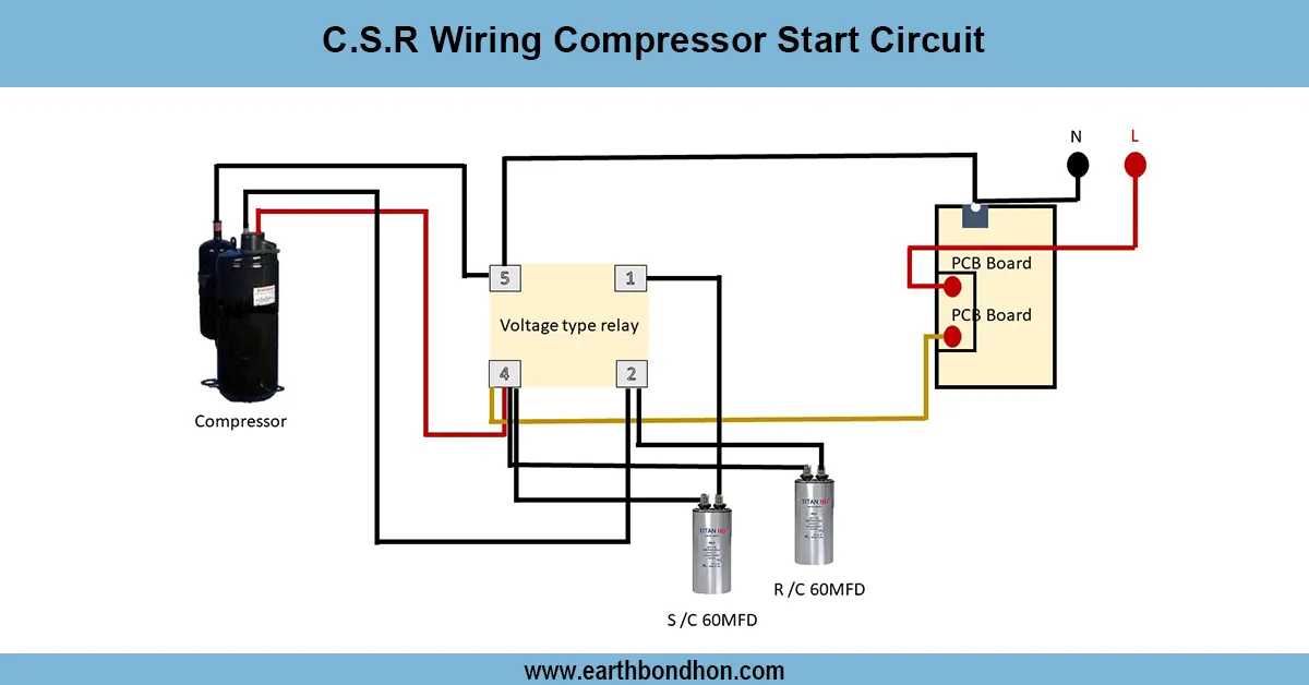
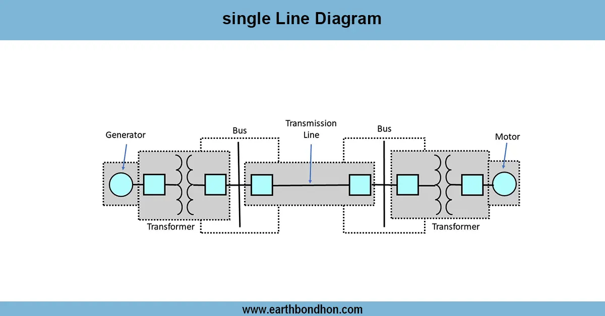
Components: Two SPDT switches, motor, power supply (live, neutral, ground), traveler wires.
Connections: Live supply connects to common terminal of Switch 1; traveler wires connect Switch 1 and Switch 2; Switch 2 common terminal connects to motor supply.
Operation: Toggling either switch changes the motor supply state (ON/OFF).
Safety: Ensure proper grounding and use circuit protection devices.
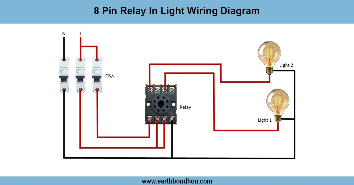
| Terminal | Connection | Function |
|---|---|---|
| Switch 1 Common (C1) | Connects to Live supply | Power input |
| Switch 1 Travelers (T1, T2) | Connect to Switch 2 travelers | Switching paths |
| Switch 2 Common (C2) | Connects to Motor Live input | Power output |
| Motor Neutral | Connects to Neutral line | Completes circuit |
| Earth (Ground) | Connects to Motor Frame | Safety grounding |
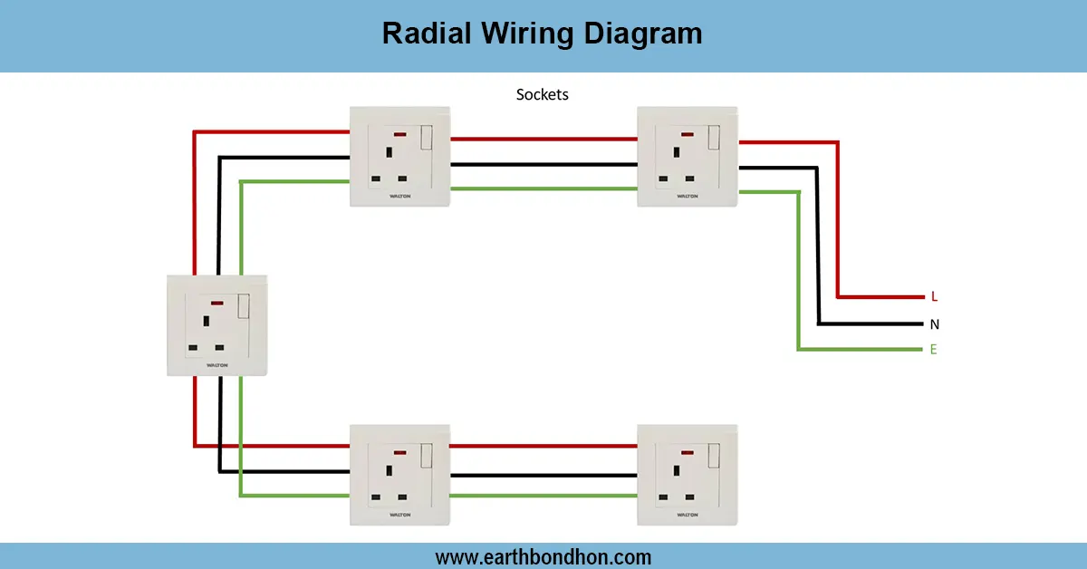
two way switch installation motor
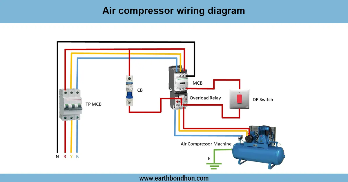
The method of wiring the motor, where two way switch is used, allows using two different locations to start and stop the motor. It comes in particular handy on motors which are located somewhere such as a workshop or on a conveyor system where there is a requirement to be able to turn the motor ON and OFF conveniently at various locations. This wiring has two SPDT switches in either 3 or 4 wire buss which are connected as traveler wires to complete the supply line to the motor starter or direct motor load. The motor is used with a distribution of neutral and ground wires to be safe. Such arrangement makes motor control less complicated and does not require complex relays or timers and improves user convenience and safety of operation.
electrical motor two way switch
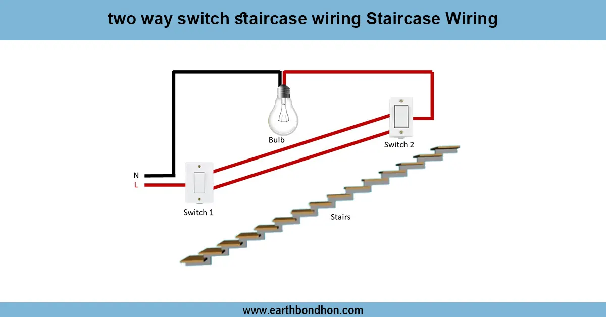
| Switch 1 Position | Switch 2 Position | Motor Status |
|---|---|---|
| Up | Up | OFF |
| Up | Down | ON |
| Down | Up | ON |
| Down | Down | OFF |