Voltage Protection Device Wiring Diagram
Learn complete electrical protection using voltage protection devices for over-voltage, under-voltage, and short-circuit safety in residential and industrial systems.

surge and short circuit protection
Voltage protection devices are used to provide electrical protection against abnormal voltages, overloads and leakage currents. RCCBs, MCBs, surge protectors, and voltage relays make homes and industries safe to operate and behave in a reliable manner.
surge protection wiring diagram
Voltage limiting devices test supply voltage, and switch the load on or off in the event of over-voltage or under-voltage. Correct installation of copper wiring will prevent damage to motors, appliances and electrical circuits.
overvoltage undervoltage protection
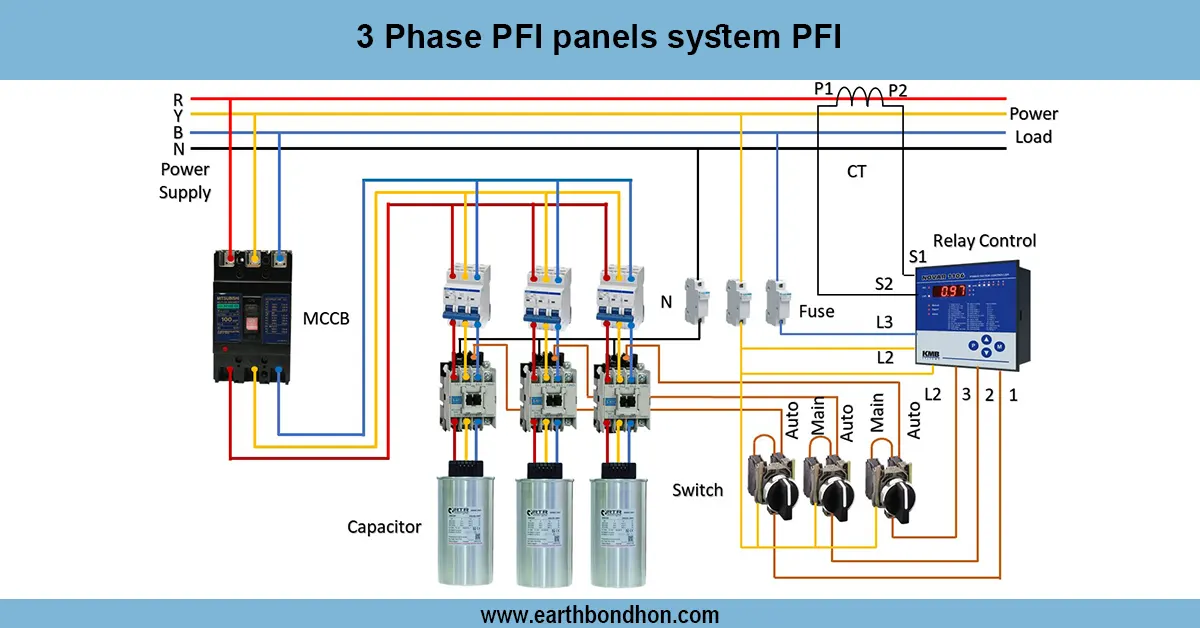
Voltage protection devices provide full electrical protection against over-voltage, under-voltage, short-circuiting, and surges of the electrical systems. The system has MCB (Miniature Circuit Breaker), RCCB (Residual Current Breaker), surge protection devices, voltage monitoring relay, and automatic cut-off switches. In domestic or industrial use, incoming AC voltage is first subjected to voltage-protecting devices, which interrupt the supply when voltages are either above or below the safe levels. MCBs deal with overcurrent or short-circuit situations, and RCCBs deal with leakage currents. Proper wiring will help in safe operation, avoiding equipment damage, and help personnel against electric shock. Installation is the process of connecting the main supply to the voltage protection devices and providing the protected power to the loads. Simulations ofover-r/under-voltage, overload, ds, and leakage currents are also tested to ensure that the protection devices are functioning properly.
voltage monitoring relay wiring
Voltage protection is a method of electrical protection that provides defense against damaging electrical variations in the electrical circuit and equipment, like over-voltage or under-voltage conditions. A voltage protection device (VPD) is one which continuously monitors supply voltage. The device will automatically switch the load on and off to avoid damage in case the voltage exceeds or drops below preset limits. Normal wiring consists of incoming supply via the device, load connection and optional bypass or alarm output. Contactors, relays and control panels are frequently combined with voltage protection devices in industrial use. Correct installation facilitates safe working of sensitive equipment, motors and household appliances and avoidance of electrical hazards. Testing includes over / under voltages and testing that the device disconnects the load properly. Voltage protection devices are extensively utilized either in residential, commercial or industrial settings with the aim of improving safety and protecting equipment investment.
Work & Installation (Input → Output Summary)
- Incoming AC Supply enters voltage protection devices.
- Voltage Protection Relay monitors over-voltage and under-voltage conditions.
- MCB protects circuits from overcurrent and short circuits.
- RCCB detects leakage currents and trips to prevent shocks.
- Surge Protection Device safeguards against voltage spikes.
- Automatic Cutoff Switch disconnects supply during unsafe voltage.
- Load Distribution receives safe and regulated voltage supply.
Testing & Final Adjustments
- Verify insulation and proper connections for mains and load circuits.
- Test voltage protection relay by simulating over-voltage and under-voltage conditions.
- Check MCB operation under simulated overload or short circuit.
- Test RCCB by creating a small leakage current to ensure tripping.
- Verify surge protection device functionality with voltage spikes (simulated safely).
- Ensure the automatic cutoff switch disconnects the supply during unsafe voltage.
- Inspect all wiring for secure connections and proper earthing.
- Confirm that the load receives a stable voltage after the protection devices.
- Confirm that the load receives a stable voltage after the protection devices.
- Document results to ensure a safe and reliable electrical protection system.
Frequently Asked Questions - Voltage Protection Device Wiring Diagram:
What is voltage protection in electrical systems?
A system that protects circuits and equipment from over-voltage, under-voltage, and surges.
Which devices are used?
MCB, RCCB, voltage monitoring relay, surge protector, and automatic cutoff switch.
Why is protection necessary?
To prevent damage to electrical equipment and ensure safety of personnel.
How does over-voltage protection work?
Voltage relay disconnects supply if voltage exceeds safe limits.
How does under-voltage protection work?
Voltage relay trips supply if voltage drops below safe limits.
What does RCCB protect?
It detects leakage currents and prevents electric shock.
Where is surge protection used?
To safeguard against voltage spikes from lightning or switching.
Can this system be used at home?
Yes, suitable for residential and industrial electrical systems.
How to test the protection system?
Simulate over/under-voltage, overload, and leakage currents to check device response.
Is earthing required?
Yes, proper earthing ensures safe operation and prevents electrical hazards.
What is a voltage protection device?
A device that disconnects the load when supply voltage exceeds or drops below safe limits.
Why is voltage protection needed?
To protect equipment from damage due to over-voltage or under-voltage conditions.
Where is it used?
Residential, commercial, and industrial electrical installations.
How does it work?
It continuously monitors line voltage and trips the load if voltage goes out of preset range.
Can it protect motors?
Yes, it prevents motors from burning out due to voltage fluctuations.
Does it have an alarm?
Some devices include alarm outputs to indicate fault conditions.
Is earthing required?
Yes, for safety and proper operation of protective devices.
Can it be used with household appliances?
Yes, especially sensitive equipment like refrigerators, ACs, and computers.
How to test it?
Simulate over-voltage and under-voltage conditions and check if device disconnects the load.
Does it work automatically?
Yes, it automatically disconnects and reconnects the load based on voltage limits.