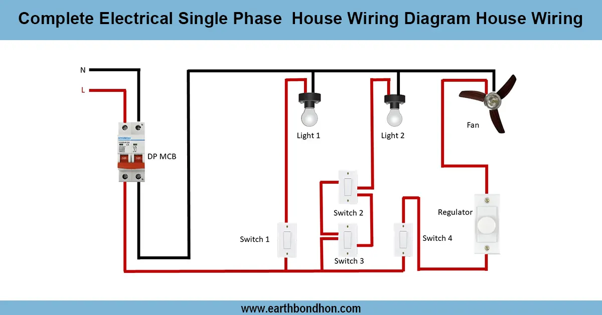

Water pump control from two places
Step-by-step wiring diagram for controlling a water pump from two different locations using two-way switches, ensuring convenience and safety.

two switch water pump wiring diagram
Wall-mount switches (those used in appliances such as clothes dryers) mount to the wall on screws and have a number of switch leg connections. Two-way switch wiring allows one to control the power to a water pump motor at two different locations, by connecting multiple switches which indicate power on or off by opening or closing each switch leg. It is a system which suits the operation of flexible pumps with increased safety.
Formula & Table Summary:
Logic:
Pump toggles ON/OFF each time either switch is flipped.
Wiring: Two two-way (SPDT) switches connected with traveler wires; pump motor powered via relay or contactor.
Power: 230 V AC with proper earthing and fuse protection.
Safety: Use contactor for motor switching and ensure all wiring insulation meets standards.
| Component | Connection | Notes |
|---|---|---|
| Two-Way Switch 1 | Connected to line supply and traveler wires | Located at first control point |
| Two-Way Switch 2 | Connected to traveler wires and relay coil | Located at second control point |
| Relay Coil | Powered by two-way switch output | Controls pump motor power |
| Pump Motor | Powered via relay contact | Starts/stops on switch toggle |
| Power Supply | 230 V AC Line, Neutral, Earth | Main supply to the system |
water pump on/off multiple switches
A two-way switch wiring system can be used in controlling water pump in two distinct places. The approach is convenient when applicable in large homes or farms where the pump should rather be operated at various locations, such as the location where the water tank is and the location of the electric panel. It has two two way switches wired a certain way so that the pump can be switched ON and OFF whether you use either of the two switches. The two-way switches supply pump motor power via a relay or a contactor which will safely operate higher loads. This arrangement is less complex to work with, since there is less wiring, as well as more convenient to the user than separate controls. It should be handled with proper fuse, earth grounding, and safety considerations to have a reliable and a safe use.
water pump on/off multiple switches
| Switch 1 Position | Switch 2 Position | Pump State | Remarks |
|---|---|---|---|
| Up | Up | OFF | Pump off, both switches aligned |
| Up | Down | ON | Pump on, switches in opposite positions |
| Down | Up | ON | Pump on, switches in opposite positions |
| Down | Down | OFF | Pump off, both switches aligned |