Single Phase Submersible Pump Wiring Diagram:
This diagram shows how to make Single Phase Submersible Pump Wiring. In this circuit, we use a single-phase submersible pump, a total of 2 wire connectors, a capacitor, a DPST switches, and an overload relay. This circuit diagram is very easy to connect and very simple to make. If you want to know more about this circuit please check our youtube video at the below post.
Advertisements
Diagram of Single Phase Submersible Pump Wiring:

Components needed For this Project:
You can get the components from any of the sites below:
- single phase Submersible water pump (1 HP) [See Buy Click Amazon]
- Terminal Block [See Buy Click Amazon]
- DPST Switch [See Buy Click Amazon]
- Refrigerator Overload [See Buy Click Amazon]
- 50 MFD Capacitor (220V ac Line) [See Buy Click Amazon]
*Please note: These are affiliate links. I may make a commission if you buy the components through these links. I would appreciate your support in this way!
Advertisements
Components used to make the Single Phase Submersible Pump Wiring:
01. Single Phase Submersible Pump:
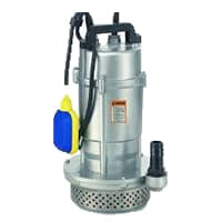
A Submersible Pump Is an Air-Tight Sealed Motor Close-Coupled to The pump is body. The Main Advantage of This Type of Pump is That it Prevents Pump Cavitation, a Problem Associated With a High Elevation Difference Between the submersible Pump and the Fluid Surface. Submersible Pumps As The Name Suggests Are made To Be fully Submerged in Water. It is a Centrifugal Water Pump, Meaning It Has a Motor That Powers An impeller Designed to Rotate And Push Water Outwards. The Motor is located Within a Waterproof Seal and is Closely Coupled to The body of The Pump That it Powers.
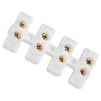
02. Wire Connector:
Terminal Clocks are Connectors That Terminate a Single wire and Connect it to a circuit or other system. Terminal Blocks come in a range of shapes, Sizes, and ratings, but Always Terminate a single Wire and are Never multi-pole. Terminal Blocks are used to Secure or Terminate Wires and, in Their Simplest form, Consist of Several Individual Terminals Arranged in a long strip system. Terminals are Useful for Connecting the Wiring to the GND or, in the Case of Electrical power, for Connecting Electrical Switches and Outlets to the Mains side.
03. DPST Switch:

DPDT With two poles and two throws for each pole, the DPDT switch has six terminals — 2 inputs and four outputs (or 2 outputs for each individual circuit). A DPDT switch controls 2 separate circuits with the same actuator. which is generally designed for an on-on or on-off-on function. DPDT or Double pole, double throw switches will break or make the 2 conductors connected to 2 separate circuits. In this switch. DP switches control 2 independent circuits whereas DT switches close a circuit in the up & down position.
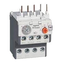
04. Overload Relay:
Overload Protection is Protection Against a Running Overcurrent That Would Cause Overheating of The Protected Equipment. Hence, An Overload is Also a Type of Overcurrent flow. Overload Protection Typically Operates on an Inverse Time curve where the Tripping Time Becomes less as the Current Increases. This Overload Protector is an Essential Component for Many Sockets Power Systems. The Top-Quality Overload Protector can Effectively Protect Electrical Products from Power Surges.
05. Capacitor:

Motor Starting Capacitors are used during the Motor Startup Phase and are Disconnected From the Circuit once the Rotor Reaches a Predetermined Speed, Which is Usually about 75% of the Maximum Speed for that Motor type. These Capacitor Usually Have Capacitance Values Of Over 70 UF. The Starting capacitor creates a Current-to-Voltage lag in the Separate start Windings of the Motor. Starting Capacitor are Wired into The Auxiliary Winding Circuit of the Motor and are Disconnected from the main winding circuit by the Centrifugal Switch once the Motor has Reached a Predetermined Speed.
Thank You for visiting the website. Keep visiting for more Updates.
Frequently asked questions
Single-phase motors are primarily used in cases when the motor is going to be turned on and off multiple times in a day. Single-phase motors also find extensive usage in remote locations where electricity is not easily available from the electrical grid.
1 HP Single Phase Submersible Pump, Maximum Discharge Flow (LPM): 100 - 500 LPM.
AC Solar Submersible Pumpset uses alternating current as their power source, which is available on almost every power grid. An inverter could also be used in a situation where the power supply source is DC. DC Solar Submersible Pumpset, on the other hand, requires Direct Current to operate, which is derived from solar panels.
The pumping power supply is calculated as the volume of the fluid per unit time (flow capacity) times the density of the fluid times the gravitational constant times the pumping head (vertical distance to be pumped). Pumping energy is simply a power supply multiplied across time.
The larger ones are 240V AC. Much larger ones (over 5 to 10 hp) are three-phase (240, 277, 460, etc). Most everywhere else, all motors (like all electric motors) are 240v AC until they get over about 10 kW and then they'll be three-phase.
Read more Single Phase Wiring
What is a kilowatt-hour (kWh) | kwh formula | What does kwh mean
Introduction to Electrical Units and CircuitskW and kWh on your electricity bill As your home uses electricity during...
What is the Difference Between kVA | What does KVA mean | kVA formula
Difference Between KVA ExplainedWhat does KVA Mean? There are technical terms aplenty when it comes to generators, and...
Power Factor | Power Unit | Energy | Electricity Unit
Power factor definition | Calculating Power FactorPower Factor Values In a purely resistive circuit, the power factor...
0 Comments