Submersible Motor connection:
This diagram shows how to make the submersible motor connection. In this circuit, we use an indicator light, a capacitor, an SP MCB ( Single Pole Miniature Circuit Breaker ), and a motor. First, we need to input 220v power to the motor connection. Then connect the indicator, capacitor, and MCB like in our diagram. Now this circuit is ready for use. If you want to know more about this circuit please check our youtube video below the post.
Advertisements
Diagram of Submersible Motor connection:

Components needed For this Project:
You can get the components from any of the sites below:
- SP MCB 10A [See Buy Click Amazon]
- 50 MFD Capacitor (220V ac Line) [See Buy Click Amazon]
- Indicator Light 220v AC [See Buy Click Amazon]
- Terminal Block [See Buy Click Amazon]
*Please note: These are affiliate links. I may make a commission if you buy the components through these links. I would appreciate your support in this way!
Advertisements
Components used to make the Submersible Motor connection:
01. SP MCB:

In single-pole MCB, Switching and protection are Affected in only one Phase. Single phase supply to break the phase only. A single Pole breaker is Typically used with 120-volt Circuits, and a 6-20 amps Miniature Circuit Breaker. They are constructed with one Line Wire and one Neutral wire. A Single Pole switch is the most basic General-Purpose switch that you use to Control a light or another device from one location. These Switches have 2 Brass-Colored screw Terminals Connected to the hot Power source wires. Pole refers to the number of Circuits Controlled by the Switch SP Switches Control only one Switch Electrical Circuit.
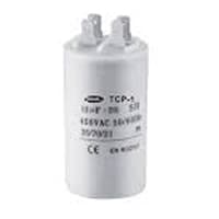
02. Capacitor:
Motor Starting Capacitors are used during the Motor Startup Phase and are Disconnected From the Circuit once the Rotor Reaches a Predetermined Speed, Which is Usually about 75% of the Maximum Speed for that Motor type. These Capacitor Usually Have Capacitance Values Of Over 70 UF. The Starting capacitor creates a Current-to-Voltage lag in the Separate start Windings of the Motor. Starting Capacitor are Wired into The Auxiliary Winding Circuit of the Motor and are Disconnected from the main winding circuit by the Centrifugal Switch once the Motor has Reached a Predetermined Speed.
03. Indicator:
An indicator lamp just Sounds Technical, Sometimes it is called a Supervisory light Indicator. Indicator lights are amber in color and can be located at the Front, the Rear, and Sometimes at the Side of the car on both the left And Right-hand sides. The Common colors used by Indicator lamps are red, yellow, blue, white, and green line system. A Panel Indicator Lamp Generally has up to 5 Differently Colored Segments to Indicate Various Conditions on the Machine or Process system.

04. Terminal Block:
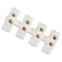
Terminal Clocks are Connectors That Terminate a Single wire and Connect it to a circuit or other system. Terminal Blocks come in a range of shapes, Sizes, and ratings, but Always Terminate a single Wire and are Never multi-pole. Terminal Blocks are used to Secure or Terminate Wires and, in Their Simplest form, Consist of Several Individual Terminals Arranged in a long strip system. Terminals are Useful for Connecting the Wiring to the GND or, in the Case of Electrical power, for Connecting Electrical Switches and Outlets to the Mains side.
Thank You for visiting the website. Keep visiting for more Updates.
Frequently asked questions
The submersible pump is completely submerged in the water and is used to push water towards the surface. The water from the well or reservoir flows into the motor through the foot valve and strikes the impeller, which has multiple fixed blades.
During the installation, you will run piping from the well to your home and structure where the water will be used. Crimp You will use crimp connectors to securely connect the piping to the well motor.
These motors are suitable for Drinking Water Applications Due to More Hygienic Operations. This is a Three-phase pump. This submersible motor is connected with motors for proper evacuation of water. This motor is known for its durability and high performance.
There are many types of submersibles, including both human-occupied vehicles (HOVs) or uncrewed craft, variously known as remotely operated vehicles (ROVs) and unmanned underwater vehicles (UUVs).
Anything that functions in the water could be described this way, including a submarine, which is sometimes actually called a submersible. The word comes from the Latin submerge, "to plunge under or sink," from the root words sub, "under," and merger, "to plunge or immerse."
Read more Single Phase Wiring
What is a kilowatt-hour (kWh) | kwh formula | What does kwh mean
Introduction to Electrical Units and CircuitskW and kWh on your electricity bill As your home uses electricity during...
What is the Difference Between kVA | What does KVA mean | kVA formula
Difference Between KVA ExplainedWhat does KVA Mean? There are technical terms aplenty when it comes to generators, and...
Power Factor | Power Unit | Energy | Electricity Unit
Power factor definition | Calculating Power FactorPower Factor Values In a purely resistive circuit, the power factor...
Very helpful post and diagram. Thanks for sharing with us.