3-phase motor to single-phase wiring diagram:
This diagram shows how to make 3 phase motor to single-phase wiring. In this circuit diagram, we use a 3-phase motor and a motor capacitor. First, we need to input the neutral connection to the motor directly, then input the phase line to the capacitor and motor like in our diagram. And again connect the capacitor to another connection with the motor. Now our circuit is ready for use. If you want to know more about this circuit please check our youtube video below the article.
Advertisements
Diagram of the 3-phase motor to single-phase wiring diagram:

Components needed For this Project:
You can get the components from any of the sites below:
*Please note: These are affiliate links. I may make a commission if you buy the components through these links. I would appreciate your support in this way!
Advertisements
Components used to make the 3-phase motor into single phase wiring diagram:
01. 3 Phase Motor:

A 3-phase electric motor uses a 3-phase Power Supply to Convert Electric Energy into Mechanical Energy. It contains four Wires (Three hot Wires and one Neutral Wire) and Uses 3 Alternating Currents of the Same Frequency. Since it Generates a Rotating Magnetic Field, it does not need a Capacitor for the Startup. Some 3-phase Motors are Reversible, Which Means they can serve as Generators by Turning Mechanical Energy into Electrical Energy.
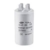
02. Capacitor:
Motor Starting Capacitors are used during the Motor Startup Phase and are Disconnected From the Circuit once the Rotor Reaches a Predetermined Speed, Which is Usually about 75% of the Maximum Speed for that Motor type. These Capacitor Usually Have Capacitance Values Of Over 70 UF. The Starting capacitor creates a Current-to-Voltage lag in the Separate start Windings of the Motor. Starting Capacitor are Wired into The Auxiliary Winding Circuit of the Motor and are Disconnected from the main winding circuit by the Centrifugal Switch once the Motor has Reached a Predetermined Speed.
Thank You for visiting the website. Keep visiting for more Updates.
Frequently asked questions
The single-phasing could occur as a result of a fuse blowing or protective device opening on 1 phase of the pump. Other possibilities include feeder and step-down transformer fuses blowing.
A phase converter could be wired directly to whatever motor you're trying to convert. You will 1 run 2 wires from the motor to the converter and then from the converter to your power supply.
Because of this design, three-phase pumps have significantly higher efficiency at converting electrical to mechanical energy, and therefore lower operating costs. They are inherently self-starting, or because of their higher torque, especially during starting, they are ideal for heavy industrial applications.
Can three-phase products be used in single phases? A. Yes, they can. It is up to the customer what number of the terminal is to be free but please be careful so that the wires are not crossed.
Single-phase power supply has two wires; an active and a neutral. It supplies power supply at around 240 v and is used in homes and businesses for most appliances and lighting. 3 phase power supply has 4 wires; three actives and one neutral, and supplies power supply at both 240V and 415V.
Read more Single Phase Wiring
What is a kilowatt-hour (kWh) | kwh formula | What does kwh mean
Introduction to Electrical Units and CircuitskW and kWh on your electricity bill As your home uses electricity during...
What is the Difference Between kVA | What does KVA mean | kVA formula
Difference Between KVA ExplainedWhat does KVA Mean? There are technical terms aplenty when it comes to generators, and...
Power Factor | Power Unit | Energy | Electricity Unit
Power factor definition | Calculating Power FactorPower Factor Values In a purely resistive circuit, the power factor...
0 Comments