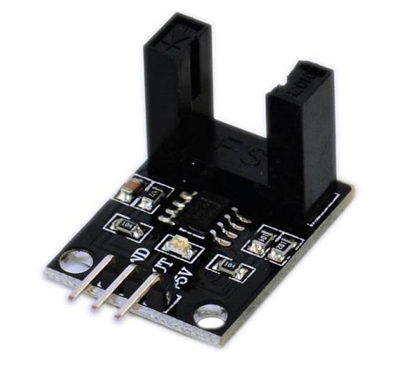
Motor Speed Sensor Arduino Speed Module
There may be a motor speed sensor module, the main goal is to see the speed of an electrical motor. The module is often utilized in association with a microcontroller for motor speed detection, pulse count, position limit, etc. In theory, any rate meter simply measures the speed at which some event occurs. Usually, this is often done by counting the events for a given period of your time (integration interval) and then simply dividing the number of events by the time to urge the speed.
There may be a motor speed sensor module, the main goal is to see the speed of an electrical motor. The module is often utilized in association with a microcontroller for motor speed detection, pulse count, position limit, etc. In theory, any rate meter simply measures the speed at which some event occurs. Usually, this is often done by counting the events for a given period of your time (integration interval) and then simply dividing the number of events by the time to urge the speed.
Pinout of Speed Sensor
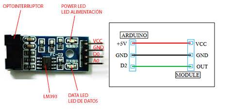
- Connect Vcc: 5v power supply.
- Ground: Ground pin of power supply.
- Aout: Analog pin of pic microcontroller.
- Dout: Digital pin of pic microcontroller.
Features
Specification:
- Groove width 10 mm.
- the working voltage of 3.3 V to 5 V
- output form: digital switch output (0 and 1)
- PCB size: 2.3 cmx2cm
- use the LM393 wide voltage comparator