Change Over With Electric Motor Wiring:
This diagram shows how to make Changes Over With Electric Motor wiring. In this circuit, we use FP MCB ( Four Pole Minature Circuit Breaker ), two magnetic contactors, a 3 phase motor, and a selector switch. First, we need to connect the FP MCB with the power source, then connect the magnetic contactor, then connect the 3-phase motor with the power source.
Advertisements
Diagram of 3 phase changeover switch wiring diagram:

Components needed For this Project:
You can get the components from any of the sites below:
- FT MCB 30A [See Buy Click Amazon]
- Magnetic Contactor 40A [See Buy Click Amazon]
- Selector Switch (220V AC) [See Buy Click Amazon]
- 3 Phase Motor (5 HP) [See Buy Click Amazon]
*Please note: These are affiliate links. I may make a commission if you buy the components through these links. I would appreciate your support in this way!
Advertisements
Components used to make the Change Over With Electric Motor wiring:
01. TP MCB:
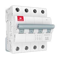
4 pole MCB for 4-Wires Connections, the one additional 4th pole for Neutral Wire Connection so that between Neutral and any of the other three will supply. In 4-Pole MCB the Neutral Pole is also having Protective release as in the Phase Poles connection. 3 Phase Supply with Neutral. TPN means triple pole TP + Neutral which is 3 - phases and Neutral. but the Protection is given for 3 Phases only and in 4 poles MCB Protection is given to all 3-Phases as well as Neutral. In the case of a 4-pole MCB. A Purpose is not to protect the Neutral but it is rather to Isolate the Neutral.
02. Magnetic Contactor:
A magnetic contactor is an electromagnetic switching device. It is generally used for controlling 3-phase Motors. The operation of a magnetic contactor is similar to that of a Relay. but a relay is used for low-power or low-voltage connections, and a magnetic contactor is used for high-power or high-voltage connections. As soon as the supply is applied to the magnetic contactor coil. its normally open contacts are closed and normally closed contacts are opened and the associated devices are also operated. This is how a magnetic contactor works.

03. Selector Switch:
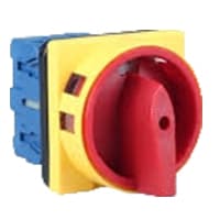
A Mechanical Switch That can be rotated Left, right, or center to open or close the Electrical contacts is known as a Selector switch. The Main Function of This Selector Switch is to Control Devices and also to Switch Between a Minimum of 2 or Above Electrical Circuits. The Perfect Used for Selector Switch is When Used for Controlling the Output of a Device. We know that a Selector switch is Used to control the electrical current flow in a Circuit it can also be used to both Initiate and inhibit the Current Flow.
04. 3 Phase Motor:
A 3-phase electric motor uses a 3-phase Power Supply to Convert Electric Energy into Mechanical Energy. It contains four Wires (Three hot Wires and one Neutral Wire) and Uses 3 Alternating Currents of the Same Frequency. Since it Generates a Rotating Magnetic Field, it does not need a Capacitor for the Startup. Some 3-phase Motors are Reversible, Which Means they can serve as Generators by Turning Mechanical Energy into Electrical Energy.

Thank You for visiting the website. Keep visiting for more Updates.
Frequently asked questions
An automatic phase change-over switch is designed primarily to disconnect the load from its power supply source and transfer it to a standby source say a generator, in case there is a power outage. The switching process is done in a controlled manner so as to prevent the false starting of the generator at very short power supply outages.
A changeover switch works when the main power supply grid fails and the generator needs to operate to power the home. The switch activates when the power is out and the generator's power supply will be used. This transfer of power will be done safely and will prevent any back feed which could be dangerous.
The most common changeover function relays are produced to switch a single feed line (usually Positive --position 30) between two active functions in a circuit diagram. The relay is switched manually via a toggle/push switch or remotely through the circuit diagram.
The Changeover automatically switches mains electricity from 1 supply to another. in the event of a fire or mains power supply failure, to ensure continuous supply to firefighting lifts.
In electrical systems, a changeover to the switch is used to switch the power supply from a primary source to a secondary source in the event of a power supply failure or maintenance. This ensures continuity of power supply and could be crucial for critical systems such as hospitals, data centers, or industrial facilities.
Read more Single Phase Wiring
What is a kilowatt-hour (kWh) | kwh formula | What does kwh mean
Introduction to Electrical Units and CircuitskW and kWh on your electricity bill As your home uses electricity during...
What is the Difference Between kVA | What does KVA mean | kVA formula
Difference Between KVA ExplainedWhat does KVA Mean? There are technical terms aplenty when it comes to generators, and...
Power Factor | Power Unit | Energy | Electricity Unit
Power factor definition | Calculating Power FactorPower Factor Values In a purely resistive circuit, the power factor...
0 Comments