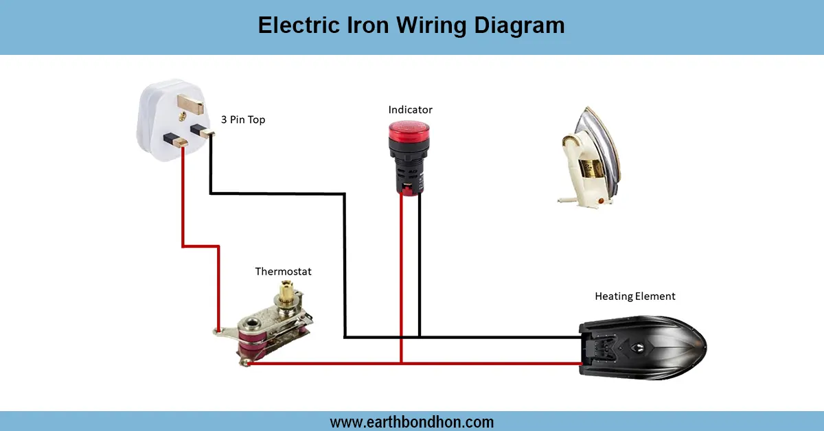


Electrical Ring socket connection
UK ring circuit wiring diagram showing socket connections, protective devices, and proper wiring method for safe and efficient power distribution.

ring main circuit diagram
A socket ring circuit wiring diagram (that of the United Kingdom) demonstrates the perfection in connecting the sockets in an ongoing loop to increase the efficiency of wiring in the distribution of the load.
Formula & Table Summary:
Formula: Ring Circuit Load = (Total Socket Load ÷ 2 Paths)
Standard Cable: 2.5mm² Twin & Earth (BS 6004)
Protection: 32A MCB or RCBO (BS EN 60898)
Voltage: 230V AC
| Component | Connection | Purpose |
|---|---|---|
| Consumer Unit | MCB/RCBO output | Protects circuit |
| Live (Brown) | To sockets in ring | Supplies voltage |
| Neutral (Blue) | To sockets in ring | Returns current |
| Earth (Green/Yellow) | To sockets in ring | Safety grounding |
UK socket ring connection
A ring circuit (sometimes referred to as a ring final circuit) is a system of wiring used for domestic and commercial installations. It is a piece of loop (ring) of cable that originates and terminates at the consumer unit and goes through several sockets. Less resistance through the cables, balanced cable loads and the ability to use smaller cable sizes (usually 2.5mm 2 ) with a 30A or 32A breaker, all are due to this design. The live (L), neutral (N) and earth (E) wires are parallel lying alongside each socket. The fuse/breaker in the consumer unit is the same fuse/breaker at the two ends of the ring, I.e. a completed loop. This means that there should be several working paths and there should be no overloading of any one section. Effective and safe installation should be in accordance with the wiring safety regulations of BS 7671.
UK socket ring connection
| Socket No. | Cable Length (m) | Load (W) |
|---|---|---|
| 1 | 5 | 500 |
| 2 | 7 | 1000 |
| 3 | 4 | 800 |