Contactors
When a relay is employed to change an oversized quantity of electric power through its contacts, it’s selected by a special name: contractor. Contractors generally have multiple contacts, and people contacts square measure sometimes (but not always) normally-open, in order that power to the load is shut off once the coil is de-energized. maybe the foremost common industrial use for contractors is that the management of electrical motors.
The top 3 contacts switch the individual phases of the incoming 3-phase AC power, generally a minimum of 480 Volts for motors one H.P. or bigger. rock bottom contact is associate “auxiliary” contact that features a current rating a lot of below that of the massive motor power contacts, however, is motivated by constant coil because of the power contacts. The auxiliary contact is usually utilized in a relay logic circuit, or for a few alternatives a part of the control theme, generally, shift a hundred and twenty potential units AC power rather than the motor voltage. One contractor could have many auxiliary contacts, either normally-open or normally-closed if needed.
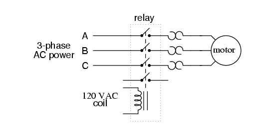
The 3 “opposed-question-mark” formed devices nonparallel with every part getting to the motor square measure known as overload heaters. every “heater” component may be a low-resistance strip of metal meant to heat up because the motor attracts current. If the temperature of any of those heater parts reaches a juncture (equivalent to moderate overloading of the motor), a normally-closed switch contact (not shown within the diagram) can spring open. This normally-closed contact is typically connected nonparallel with the relay coil, in order that once it opens the relay can mechanically de-energized, thereby movement off power to the motor. we are going to see a lot of this overload protection wiring within the next chapter. Overload heaters square measure meant to produce overcurrent protection for big electrical motors, in contrast to circuit breakers and fuses that serve the first purpose of providing overcurrent protection for power conductors.
Three-Phase Electric Motor Contactor
Three-phase, 480 VAC power comes into the 3 normally-open contacts at the highest of the contactor via screw terminals labeled “L1,” “L2,” and “L3” (The “L2” terminal is hidden behind a square-shaped “snubber” circuit connected across the contactor’s coil terminals). Power to the motor exits the overload heater assembly at rock bottom of this device via screw terminals labeled “T1,” “T2,” and “T3.
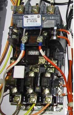
The overload heater units themselves are black, square-shaped blocks with the label “W34,” indicating a selected thermal response for an exact HP and temperature rating of the electrical motor. If an electrical motor of differing power and/or temperature ratings were to be substituted for the one presently in commission, the overload heater units would have to be compelled to get replaced with units having a thermal response appropriate for the new motor. The motor manufacturer will give info on the suitable heater units to use.
A white electrical switch situated between the “T1” and “T2” line heaters is the simplest way to manually reset the traditionally-closed switch contact back to its normal state once having been tripped by excessive heater temperature. Wire connections to the “overload” switch contact are also seen at the lower-right of the photograph, close to a label reading “NC” (normally-closed). On this specific overload unit, a tiny low “window” with the label “Tripped” indicates a tripped condition by means that of a colored flag. during this photograph, there’s no “tripped” condition, and also the indicator seems clear.
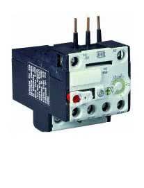
Overload Relays
The RW category ten Thermal Overload Relays, with their extended operational service lives, a square measure designed to be used with the CWC miniature and corrie commonplace contactors. These relays
Features
Phase-loss sensitivity
• Adjustable tripping current
• Tripping class 10
• Auxiliary contacts 1NO and 1NC
• Hand/Auto/Reset button
• Temperature compensation from -4°F to +140°F
• Standards and Approvals: IEC 60947, VDE 0660, cULus listed, CE Marked, Marine
Watch to Youtube Video
Read more 3 Phase Line Wiring
- 3-phase Motor Star Connection
- 3-phase kwh Meter Connection
- 3-phase Line Single-phase Meter Connection
- 3-phase Voltmeter Connection
- 3-phase Line Wiring Installation single-phase Line
- 3 Phase Motor Capacitor Star-Delta Connection
- 3 Phase Motor Control Phasing Preventer
- 3 phase Distribution Board Wiring Diagram
- 3 phase DOL Starter Motor Diagram
- Power Factor Capacitor Bank Connection
- How to use 3 phase Manual Changeover Switch