Refrigerator wiring diagram:
This diagram shows how to make a refrigerator wiring. In this circuit, we use a 3-pin plug, an indoor lamp, a door switch, a PTC starter relay, a compressor, an overload protector, and a thermostat. This circuit is very easy to connect and it s a very simple circuit. If you want to know more clear details about this circuit diagram please check our youtube video below the post.
Advertisements
Diagram of Refrigerator wiring diagram:

Components needed For this Project:
You can get the components from any of the sites below:
- Refrigerator Overload [See Buy Click Amazon]
- Thermostat Switch [See Buy Click Amazon]
- Light 220V AC [See Buy Click Amazon]
- Refrigerator Compressor [See Buy Click Amazon]
- Refrigerator PTC [See Buy Click Amazon]
- DPST Switch [See Buy Click Amazon]
- 3 Pin Plug [See Buy Click Amazon]
*Please note: These are affiliate links. I may make a commission if you buy the components through these links. I would appreciate your support in this way!
Advertisements
Components used to make the Refrigerator wiring:
01. Overload Protector:

Overload Protection is Protection Against a Running Overcurrent That Would Cause Overheating of The Protected Equipment. Hence, An Overload is Also a Type of Overcurrent flow. Overload Protection Typically Operates on an Inverse Time curve where the Tripping Time Becomes less as the Current Increases. This Overload Protector is an Essential Component for Many Sockets Power Systems. The Top-Quality Overload Protector can Effectively Protect Electrical Products from Power Surges.
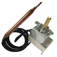
02. Thermostat:
Meaning of Thermostat The word thermo means heat and with the help of heat the Electrical circuit is switched on and off is called a thermostat. The thermostat switch is the control device of the fridge/refrigerator. which directly or indirectly controls one or more heat sources and cooling systems to maintain the refrigerator is required temperature. The role of the thermostat is important to automate the cooling system of the fridge/refrigerator. A thermostat switch is a sensitive device that automatically converts the temperature of the refrigerator.
03. Light:
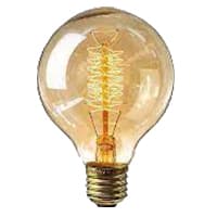
CFL stands for Compact Fluorescent Lamp which is an improved version of tube lights of earlier days. Like tube lights, it is a vacuum glass tube with fluorescent powder coating which is not as long and straight as tube lights but curved/twisted compact, or small in size. Like a tube light, it has electrodes or filaments at both ends. But in this case, instead of a choke, there is an electronic circuit that drives the Compact Fluorescent Lamp. Because the red wave is less in the light of the Tubelight and Compact Fluorescent Lamp, the object looks a little pale or the correct color of the object does not appear.
04. Compressor:
The compressor pumps gas or air from a smaller chamber to a larger chamber, thus increasing the pressure. This function is very useful in various industries, such as the petrochemical and oil industries. A compressor compresses the gas. A single phase motor converts (electrical or another form of) energy into rotary energy. A compressor is driven by or contains a single motor.

05. PTC Starter Relay:
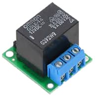
refrigerator stops producing cold air, there may be something wrong with the PTC (positive temperature coefficient) relay, also known as the start relay for coil AC 220v line. The PTC relay starts the compressor inside the fridge to make cold air so your food stays cool.PTC Thermistor Assembly or Positive Temperature Coefficient Thermistor starts the compressor motor and Is also called the Compressor Overload and Start Relay coil.
06. Door Switch:
An SPST (Single Pole Single Throw) Switch is a Switch That only Has a Single Input and can Connect Only to one Output. This means it Only Has one Input Terminal and Only 1 Output Terminal. A Switch is a Mechanical or Controlling Device That Changes the Flow of Current Direction or Interrupts the Flow of Current Within a Circuit diagram. An electrical line using Single Pole Single Throws (SPST) is Perfect for on-off switching. When the SPST is closed, the Circuit is Closed and the light from the lamp switches on the system. When The Single Pole Single Throw (SPST) is then opened, the light from the lamp goes out and the Circuit is off.

07. 3 Pin Top Plug:
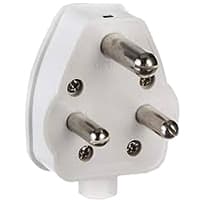
The 3-pin plug tops are used on appliances, extension leads, Light fittings, table fans, etc. The Packaging Comes with Wiring Instructions For the Electrician connection. A transparent cover makes it visually easy to Keep an Eye on the Wiring Connections electrical wire. 3-pin plugs are Designed so That Mains Electricity can be Supplied to Electrical Appliances Safely side. A 3-Pin Plug Consists of 3-pins. Each Pin Must be Correctly Connected to the 3 Wires in the Electrical Cable. Each Wire Has its Own Specified Color so that it can be easily identified power supply.
Thank You for visiting the website. Keep visiting for more Updates.
Frequently asked questions
Generally speaking, the voltage of a refrigerator should be 220 V, but it is common that the voltage can’t kept at 220V all the time, especially in rural areas. Under normal circumstances, the refrigerator could work within 187 - 242 V voltage.
Typically anywhere between 110 and 130 v will run a refrigerator. 115 to 120 v would be perfect.
A 115v or 120v, individual, properly grounded branch circuit diagram with a 3-prong grounding type receptacle, protected by a 15 or 20-amp circuit diagram breaker or time-delay fuse. Should be on a dedicated circuit. This is recommended for best performance or to prevent overloading house wiring circuit diagrams.
On average, refrigerators consume between 300 and 800 w of electricity depending on the age of the model. Most refrigerators use between 3 and 6A and operate at around 120v.
A modern refrigerator requires a dedicated 20-amp circuit. You may currently have a smaller refrigerator plugged into a general lighting circuit, but during any major remodeling, install a dedicated circuit (120/125 volts) for the refrigerator.
Read more Single Phase Wiring
What is a kilowatt-hour (kWh) | kwh formula | What does kwh mean
Introduction to Electrical Units and CircuitskW and kWh on your electricity bill As your home uses electricity during...
What is the Difference Between kVA | What does KVA mean | kVA formula
Difference Between KVA ExplainedWhat does KVA Mean? There are technical terms aplenty when it comes to generators, and...
Power Factor | Power Unit | Energy | Electricity Unit
Power factor definition | Calculating Power FactorPower Factor Values In a purely resistive circuit, the power factor...
0 Comments