Single Phase House Wiring:
This diagram shows how to make Single Phase House Wiring. In this circuit, we use a single-phase energy meter, a main switch box, two lights, a ceiling fan, two sockets, four switches, a fan regulator, and an indicator light. First, we need to input power to the single-phase energy meter, then input the power line to a main switch box, then input phase connection to all switches, fan regulators, indicators, and sockets. Then input neutral to sockets, lights, and fan neutral point. Input phase line to lights and fan from switches. Now this circuit is ready for use. If you want to know more about this circuit please check our youtube video below the post.
Advertisements
Diagram of Single Phase House Wiring:

Components needed For this Project:
You can get the components from any of the sites below:
- Single Phase Energy Meter [See Buy Click Amazon]
- Main Switch [See Buy Click Amazon]
- SPST Switch [See Buy Click Amazon]
- Gang Socket [See Buy Click Amazon]
- Board Indicator [See Buy Click Amazon]
- Ceiling Fan 56-Inch [See Buy Click Amazon]
- CFL Light [See Buy Click Amazon]
- Fan Regulator [See Buy Click Amazon]
*Please note: These are affiliate links. I may make a commission if you buy the components through these links. I would appreciate your support in this way!
Advertisements
Components used to make the Single Phase House Wiring:
01. Single Phase Energy Meter:
A Single-Phase Energy Meter is a sort of Watt-Hour meter. It consists of two Electromagnets. Single-Phase Energy Meter is also Popularly known as a watt-hour meter. 1 Magnet is called the shunt magnet Ml which is Mounted with a Pressure coil. The Pressure coil is a long coil Made of fine Copper wire that is connected across the Supply single-phase line. Single-phase energy meters are suitable for measuring single-phase AC current flow frequencies of 50/60 Hz, which are used for fixed indoor installation systems.

02. Main Switch Box:
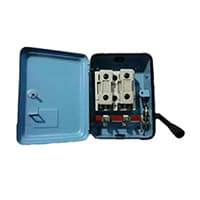
The Main Switch is Connected to the live and Neutral Wires. It is Used to Cut the Connections of the Live Wire as well as the Neutral Wire Simultaneously from the Main Supply. The main switch Isolates the Electrical supply from the whole installation so that it can be turned off for Servicing or Maintenance. It also provides overload protection for the mains cables (on newer switchboards) so that they will trip if the cable is Drawing too Much Power.
03. Switch:
An SPST (Single Pole Single Throw) Switch is a Switch That only Has a Single Input and can Connect Only to one Output. This means it Only Has one Input Terminal and Only 1 Output Terminal. A Switch is a Mechanical or Controlling Device That Changes the Flow of Current Direction or Interrupts the Flow of Current Within a Circuit diagram. An electrical line using Single Pole Single Throws (SPST) is Perfect for on-off switching. When the SPST is closed, the Circuit is Closed and the light from the lamp switches on the system. When The Single Pole Single Throw (SPST) is then opened, the light from the lamp goes out and the Circuit is off.

04. Socket:
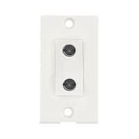
A Power Socket is a Device to Which Electrical Devices Can Be Connected to Receive the Electric Current Required For Their Operation. Connected by a System of Cables to a Power Source, Usually, an Electricity Generation Facility operated by an energy Production company, generally has no moving parts. Instead, it contains metal strips that make contact with the prongs of an Electric plug inserted into the socket. It is Through these Contacts That the Electric current is Transmitted. Electrical Devices that connect to a Power Source Through a Power Socket are Considered to be Portable Because they can easily be Connected and Disconnected From the Power Source.
05. Indicator:
An indicator lamp just Sounds Technical, Sometimes it is called a Supervisory light Indicator. Indicator lights are amber in color and can be located at the Front, the Rear, and Sometimes at the Side of the car on both the left And Right-hand sides. The Common colors used by Indicator lamps are red, yellow, blue, white, and green line system. A Panel Indicator Lamp Generally has up to 5 Differently Colored Segments to Indicate Various Conditions on the Machine or Process system.

06. Ceiling Fan:
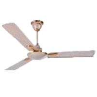
A Ceiling Fan is a fan Mounted on the Ceiling of a Room or space, Usually, Electrically Powered, That Uses hub-mounted Rotating Blades to Circulate air flow. They cool people effectively by increasing speed. It Doesn not Cool the Air Temperature — we Feel Cooler Because the Fan Moves the Air Around Us, a Process Called Evaporative Cooling. Evaporative Cooling Works like this: A cold day will feel Even Cooler if There is a Breeze Because of the wind Chill Factor.
07. Light:
CFL stands for Compact Fluorescent Lamp which is an improved version of tube lights of earlier days. Like tube lights, it is a vacuum glass tube with fluorescent powder coating which is not as long and straight as tube lights but curved/twisted compact, or small in size. Like a tube light, it has electrodes or filaments at both ends. But in this case, instead of a choke, there is an electronic circuit that drives the Compact Fluorescent Lamp. Because the red wave is less in the light of the Tubelight and Compact Fluorescent Lamp, the object looks a little pale or the correct color of the object does not appear.

08. Fan Regulator:
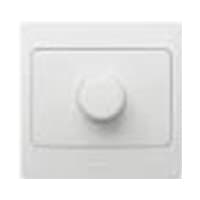
A Fan Speed Controller Controls The Voltage Across the Fan and Therefore Indirectly Controls its speed 220v AC line. A ceiling Fan Speed Regulator Actually Measures and Regulates the Speed of the Fan Using its Tachometer. Fan Speed is Controlled with Thyristor or Transformer Speed Controllers for Ceiling fans, and table fans. the fan is Controlled by a Capacitor, and the Voltage across the fan Determines the fan speed. A Speed Control loop Can be Implemented That is Independent of Manufacturing Variances and Wear on The Fan control system.
Thank You for visiting the website. Keep visiting for more Updates.
Frequently asked questions
Single-phase power is a two-wire alternating current (AC) power circuit. Typically, there is 1 power supply wire—the phase wire—and 1 neutral wire, with current flowing between the power supply wire (through the load) and the neutral wire.
When it comes to distributing power, a single-phase connection uses neutral and phase wires. The neutral wire acts as a returning path for the circuit diagram current and the phase wires carry the load. In a single-phase connection, the project system voltage starts at 230 Volts and has a frequency of about 50 Hertz.
Residential electricity and service in the power supply United States (120/240 Vac) is sometimes called 2-phase service but this is NOT correct. It is only single-phase, since both line voltages are derived from a single phase of a distribution transformer with a center tapped neutral and are 180° out of phase with each other.
Single-phase 3-wire systems (some call them 2-phase or Edison) have 2 hot wires and a neutral wire. This is the most common residential project system in the USA. If circuit diagram you measure from hot wire to hot wire you will get 240 volts and if you measure from either hot wire to neutral you will get 120 volts.
A lot of people have a misconception that project system Air Conditioners require a 3-phase connection. This actually is not true because all ACs have motors designed to run on single-phase. Only if you have more power supply than 3 ACs that are all in use together you may need a three-phase connection.
Read more Single Phase Wiring
What is a kilowatt-hour (kWh) | kwh formula | What does kwh mean
Introduction to Electrical Units and CircuitskW and kWh on your electricity bill As your home uses electricity during...
What is the Difference Between kVA | What does KVA mean | kVA formula
Difference Between KVA ExplainedWhat does KVA Mean? There are technical terms aplenty when it comes to generators, and...
Power Factor | Power Unit | Energy | Electricity Unit
Power factor definition | Calculating Power FactorPower Factor Values In a purely resistive circuit, the power factor...
0 Comments