Introduction
The objective of this post is to elucidate the thanks to transferring Associate in Nursing Arduino program to the ESP-WROOM-32 module, from DFRobot.
We will cowl in extra detail the hardware configuration needed to transfer a program to the module. you may register extra detail the thanks to modifying the support for the ESP32 among the Arduino IDE on this previous post.
Please note that this is {often|this can be} often the Associate in Nursing ESP32 module applicable for integration in electronic designs and not a development board for testing/development. Thus, the pin spacing is very little and it desires some special manual attachment skills to be able to use it. Naturally, these styles of spacing unit adequate for non-manual attachment procedures
In this code, we’re controlling an LED connected to GPIO 23.
So, connect an LED to your ESP32 by following the next schematic diagram.Important: always check the pinout for your specific board before building any circuit.
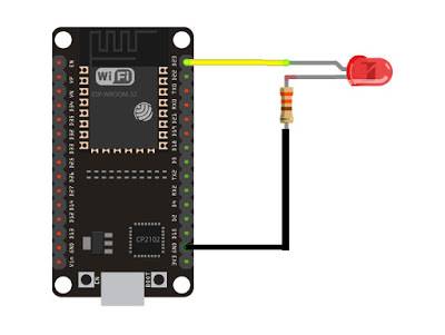
To show you how to upload code to your ESP32 board, we’ll build a simple example to blink an LED.
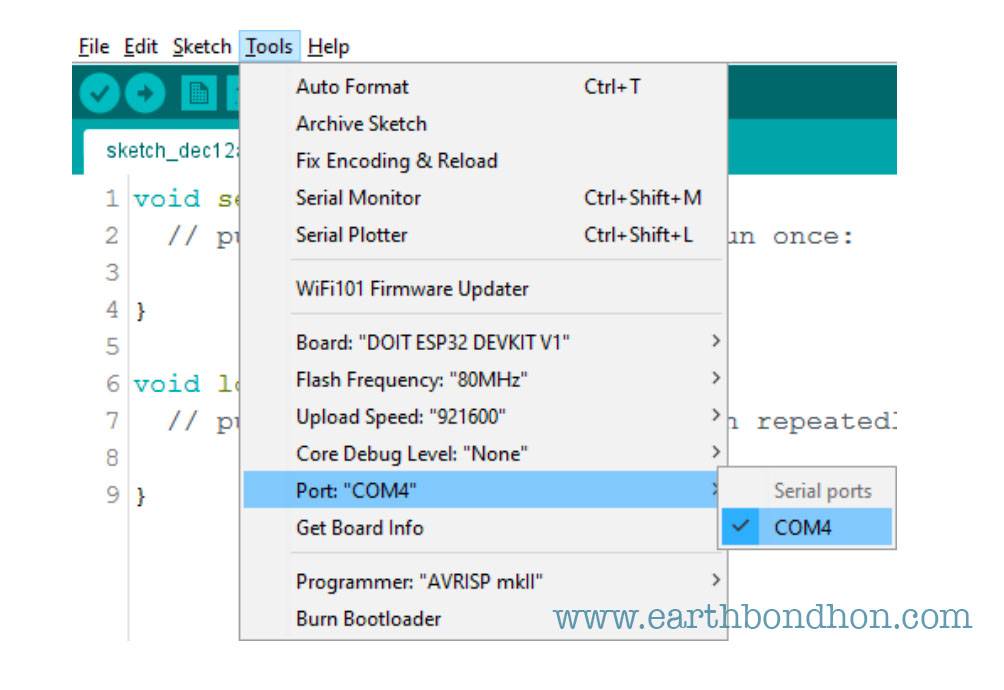
- Go to Tools > Board, scroll down to the ESP32 section and select the name of your ESP32 board. In my case, it’s the DOIT ESP32 DEV Module.

2. Go to Tools > Port and select a COM4 port available.
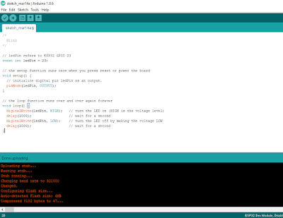
- After you see the “Connecting….” message in your Arduino IDE, release the finger from the “BOOT” button:
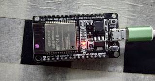
Demonstration
After uploading the code, the LED connected to GPIO 23 should be blinking every other second.
Read more Arduino Project
- pwm Signal Analog Input or Output Read
- Decode IR Remote Control Signals
- IR Remote Control Light on off
- RGB LED Control Bluetooth
- LM35 Temperature Sensor
- Bluetooth Controller Lamp
- IR Remote Servo Motor Control
- Arduino Interfacing 16×2 LCD
- Arduino ohm Meter
- Arduino ohm Meter LCD Display
- Motor Control Mosfet Using Arduino
- Smiley Faces 8×8 Matrix Display
- introducing ESP32 Board
- Installing the ESP32 Board
- ESP32 web Server