Introduction
The ACS712 provides economical and precise solutions for AC or DC current sensing in industrial, commercial, and communications systems. The device package allows for straightforward implementation by the customer. Typical applications include control, load detection and management, switched-mode power supplies, and overcurrent fault protection.
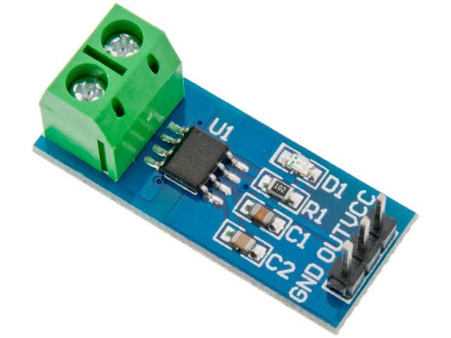
The ACS712 Module uses the famous ACS712 IC to live current using the Hall Effect principle. The module gets its name from the IC (ACS712) utilized in the module, so for you, final products use the IC directly rather than the module.
Principle:
The current sensor may be a device that detects and converts current to urge an output voltage, which is directly proportional to the present within the designed path. When current is passing through the circuit, a voltage drops across the trail where the present is flowing. Also, a magnetic flux is generated near the current-carrying conductor. These above phenomena are utilized in the present sensor design technique.
ACS712 Current Sensor Circuit Diagram
The ACS712 module has two phoenix terminal connectors (green color ones) with mounting screws as shown above. These are the terminals through which the wire has got to be passed. In our case, I’m measuring the present drawn by the motor therefore the wires that are getting to the load (motor) are skilled the ACS 712 Module. confirm the module is connected serially with the load and be extra cautious to avoid shorts.
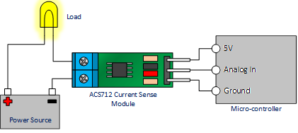
On the opposite side, we’ve three pins. The Vcc is connected to +5V to power the module and therefore the ground is connected to the bottom of the MCU (system). Then the analog voltage given out by the ACS712 module is read using an analog pin on the Microcontroller.
Specifications:
- Scale Factor.
- Measures both AC and DC current.
- It provides isolation from the load.
- Available as 5A, 20A and 30A module.
- Easy to integrate with MCU, since it outputs an analog voltage.
Features And Benefits:
- 80 kHz bandwidth.
- Low-noise analog signal path.
- 5.0 V, single-supply operation.
- Device bandwidth is set via the new FILTER pin.
- Total output error 1.5% at TA = 25°C.
- Small footprint, low-profile SOIC8 package
- 1.2 mΩ internal conductor resistance.
- 66 to 185 mV/A output sensitivity.
- Factory-trimmed for accuracy.
- Extremely stable output offset voltage.
- Nearly zero magnetic hystereses.
- 5 μs output rise time in response to step input current.
- Ratiometric output from the supply voltage.
- Output voltage proportional to AC or DC currents.
- 2.1 kV RMS minimum isolation voltage from pins 1-4 to pins 5-8.