What is a Flex Sensor?
The Flex Sensor may be a variable flexible carbon resistor. As a variable printed resistor, the Flex Sensor achieves great form-factor on a skinny flexible substrate. When the substrate is bent, the sensor produces a resistance output correlated to the bend radius the smaller the radius, the upper the resistance value.
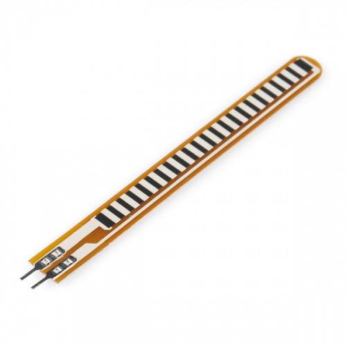
A flex sensor may be a quite sensor that’s wont to measure the quantity of defection otherwise bending. The designing of this sensor is often done by using materials like plastic and carbon. The carbon surface is arranged on a plastic strip as this strip is turned aside then the sensor’s resistance is going to be changed. Thus, it’s also named a bend sensor. As its varying resistance are often directly proportional to the number of turns thus it also can be used sort of a goniometer.
Flex sensors are in two sizes
A. 2.2 inch ( Model: FS-L-0055 ).
B. 4.5 inch.
Although the sizes are different the basic function remains the same. They are also divided based on resistance. There are LOW resistance, MEDIUM resistance and HIGH resistance types. Choose the appropriate type depending on requirement.
FLEX SENSOR WORKING
The flex sensor may be completely linear it’ll be having its nominal resistance. When it’s bent 45º angle this resistance increases to twice as before. And when the bent is 90º the resistance could go as high as fourfold the nominal resistance. therefore the resistance across the terminals rises linearly with bent angle. So during a sense, the Flex sensor converts flex angle to resistance. For convenience, we convert this resistance into voltage.
Voltage Divider Circuit Diagram:
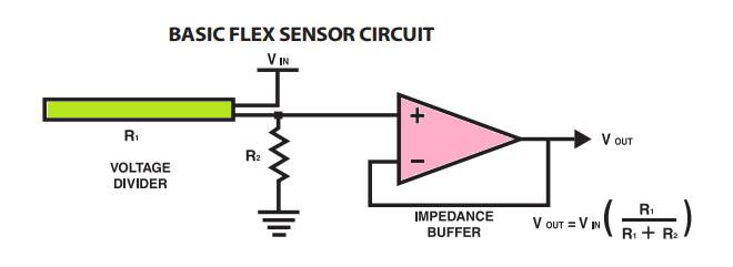
In this resistive network, we’ve two resistances. One is constant resistance (R1) and therefore the other is variable resistance (RV1). Vo is that the voltage at the midpoint of the potential divider circuit and is additionally the output voltage. Vo is additionally the voltage across the variable resistance (RV1).
So when the resistance value of RV1 is modified the output voltage Vo also changes. So we’ll have resistance change in voltage change with the potential divider circuit.
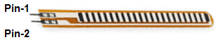
Pin Configuration
Pin P1: This pin is generally connected to the +ve terminal of the power source.
Pin P2: This pin is generally connected to the GND pin of the power source.
Specifications & Features
The specifications and features of this sensor include the following.
- Flat resistance is 25K Ω
- It can function on low-voltages.
- The tolerance of resistance will be ±30%
- Operating temperature ranges from -45ºC to +80ºC
- Operating voltage of this sensor ranges from 0V to 5V
- Power rating is 1 Watt for peak & 0.5Watt for continuous.
- The range of bend resistance will range from45K -125K Ohms
APPLICATIONS:
- Robotics
- Automotive controls.
- Medical Instruments
- Peripherals of Computer
- Virtual Motion (Gaming)
- Musical Instruments
- Industrial controls.
- Computer peripherals.
- Fitness products.
- Musical instruments.
- Measuring devices.
- Virtual reality games.
- Consumer products.
- Physical therapy.