Introduction to Color Sensor
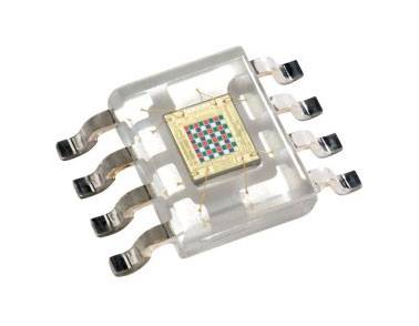
The TCS230 sensor senses color light with the assistance of an 8 x 8 array of photodiodes. Then employing a Current-to-Frequency Converter the readings from the photodiodes are converted into a square wave with a frequency directly proportional to the sunshine intensity. Finally, using the Arduino Board we will read the square wave output and obtain the results for the color. The TCS3200 color sensor can detect a good sort of color supported by their wavelengths. This sensor is particularly useful for color recognition projects like color matching, color sorting, test strip reading.
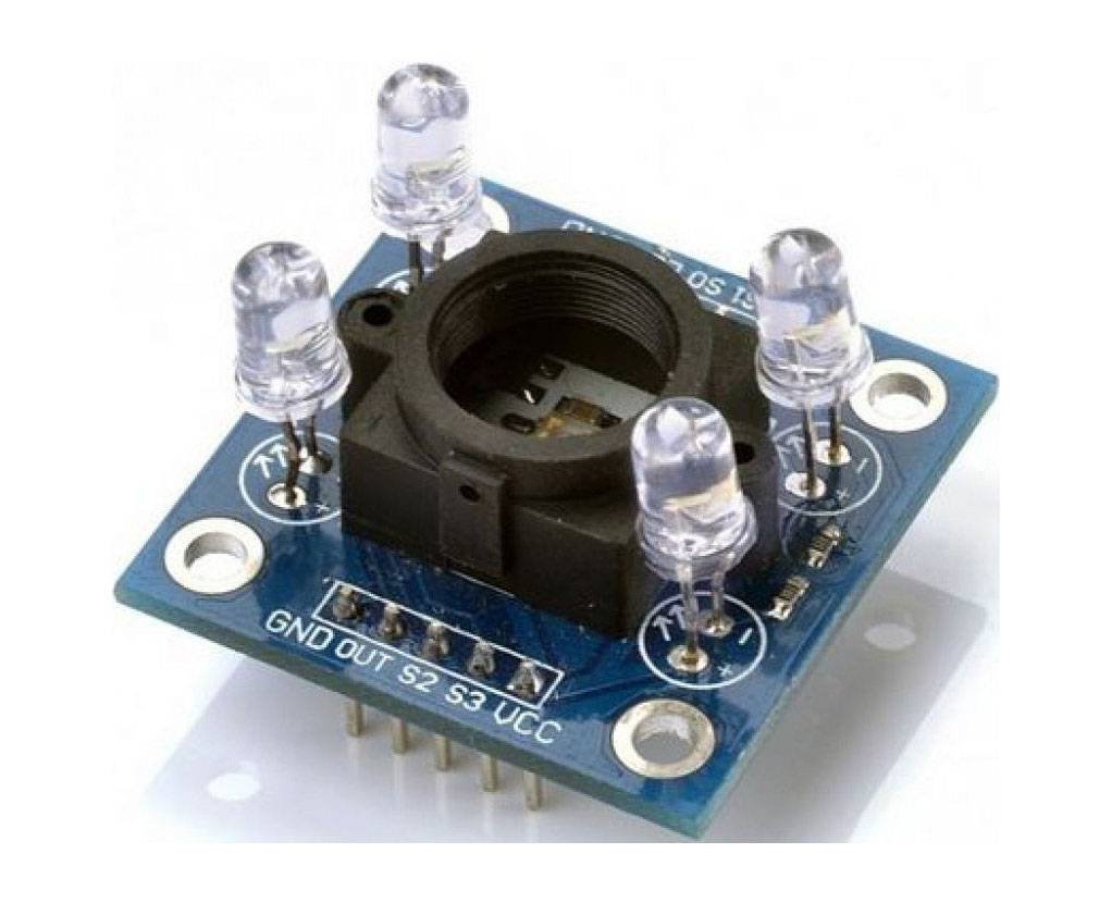
The TCS3200 color sensor – shown within the figure below – uses a TAOS TCS3200 RGB sensor chip to detect color. It also contains four white LEDs that illuminate the thing ahead of it.
Working Principle of Color Sensor
To detect the color of fabric three main sorts of equipment are required. a light-weight source to illuminate the fabric surface, a surface whose color has got to be detected and therefore the receivers which may measure the reflected wavelengths.
Colour sensors contain a white light emitter to illuminate the surface. Three filters with wavelength sensitivities at 580nm, 540nm, 450nm to live the wavelengths of red, green and blue colors respectively.
Based on the activation of those filters, the color of the fabric is categorized. a light-weight to voltage converter is additionally present within the sensor. The sensor responds to paint by generating a voltage proportional to the detected color.
Another way of detecting color is by illuminating the fabric surface by Red, Blue and Green LEDs one at a time. Here the sensor contains no filters but light to voltage converter. the very best amount of sunshine reflected back by the fabric surface while illuminated with the red, blue and green light is calculated to detect the color.
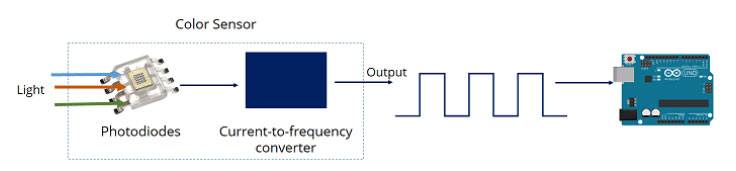
By selectively choosing the photodiode filter’s readings, you’re ready to detect the intensity of the various colors. This sensor features a current-to-frequency converter that converts the photodiodes’ readings into a square wave with a frequency that’s proportional to the sunshine intensity of the chosen color. This frequency is then, read by the Arduino – this is often shown within the figure below.
Color Sensor Pin Configuration
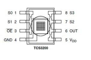
Here’s the sensor pinout:
| Pin Name | I/O | Description |
| GND (4) | Power supply ground | |
| OE (3) | I | Enable for output frequency (active low) |
| OUT (6) | O | Output frequency |
| S0, S1(1,2) | I | Output frequency scaling selection inputs |
| S2, S3(7,8) | I | Photodiode type selection inputs |
| VDD(5) | Voltage supply |
Filter selection
Take a look at the table below:
| Photodiode type | S2 | S3 |
| Red | LOW | LOW |
| Blue | LOW | HIGH |
| No filter (clear) | HIGH | LOW |
| Green | HIGH | HIGH |
FEATURES:
01. Quality tested
02. Long service life
03. Accurate functioning
SPECIFICATIONS:
01. Size: 28.4 x 28.4 mm.
02. Power Down Feature.
03. OUT Pin: Output frequency.
04. S2~S3: Photodiode type selection inputs.
05. Single-Supply Operation (2.7 V to 5.5 V).
06. Communicates Directly to Microcontroller.
07. High-Resolution Conversion of Light Intensity to Frequency.
08. Programmable Color and Full-Scale Output Frequency.
09. S0~S1: Output frequency scaling selection inputs.
10. OE Pin: Output frequency enables pin (active low), can be impending when using.
11. Support LED lamp light supplement control.